Hi,
I'm having trouble biasing a class-g circuit and was wondering if someone would be willing to help me out. As my reference I have been using this:
http://www.signaltransfer.freeuk.com/classg.htm
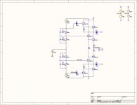
When I simulate the circuit on the link above everything works fine however when I try and insert bias generators in place of independent voltage sources things dont look so good for me.
Don't laugh at my attempt")
Thanks!
Randy
I'm having trouble biasing a class-g circuit and was wondering if someone would be willing to help me out. As my reference I have been using this:
http://www.signaltransfer.freeuk.com/classg.htm
When I simulate the circuit on the link above everything works fine however when I try and insert bias generators in place of independent voltage sources things dont look so good for me.
Don't laugh at my attempt
Thanks!
Randy
Attachments
Obviously your simulator feels like oscillating - it may be that
the real circuit would want to, but you'll never really know what
the deal is until you build it.
I don't see any capacitors across the bias generators, and I
don't see any resistance in series with the Bases of the drivers
and/or outputs. Try using some.
the real circuit would want to, but you'll never really know what
the deal is until you build it.
I don't see any capacitors across the bias generators, and I
don't see any resistance in series with the Bases of the drivers
and/or outputs. Try using some.
I currently am building a class-G Mosfet driven circuit. Well the "outer" two transistors are Mosfet's. The "inner" outputs are high current devices and have a lower breakdown voltage, hence the class-G. Just recently got it to work...yesterday.
I have yet to do any "tests" on it though. Will post...
In light of my achievements, I stupidly tried changed the voltage source for the high voltage power supply to one having a higher voltage, thinking though that it MIGHT cause breakdown, and I was right. Oops.
Oops. I don't really know what I was thinking.... Duhhh
Anyway there WAS a small construction error that aided in burning the outputs(+mosfets). But, in a hour I had it working again. This time with the right power supply voltage.
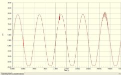
My biggest concern is if the phase shift of the signal in the Mosfet's is going to be too much at 20Khz that the two signals won't line up...the Mosfet output(collector) and the signal output. Initial tests show that around 30Khz this starts to becomes a problem. Any suggestions on how to correct this problem, if it is in fact a real concern. Don't think so but will know soon.
I have yet to do any "tests" on it though. Will post...
In light of my achievements, I stupidly tried changed the voltage source for the high voltage power supply to one having a higher voltage, thinking though that it MIGHT cause breakdown, and I was right.
Oops. I don't really know what I was thinking.... Duhhh Anyway there WAS a small construction error that aided in burning the outputs(+mosfets). But, in a hour I had it working again. This time with the right power supply voltage.
My biggest concern is if the phase shift of the signal in the Mosfet's is going to be too much at 20Khz that the two signals won't line up...the Mosfet output(collector) and the signal output. Initial tests show that around 30Khz this starts to becomes a problem. Any suggestions on how to correct this problem, if it is in fact a real concern. Don't think so but will know soon.
OK I have found that the phase relationship between the output of the mosfet's is slightly lagging at 20KHz though it is not enough to cause real problems. The real problem is that for some reason the N-ch (positive side) won't turn off as the signal decreases. The P-ch (negative side) works correctly though. Other than that, the circuit works good.
I am going to replace the fet's with darlington BJT's and see if there is any difference, careful not to exceed the SOA though! Might be better, might be worse. Should know soon. This is, after all, a learning experience.
Anyway, here is the output stage with the fet's. One current source for bias is not shown.
Other than that, the circuit works good.I am going to replace the fet's with darlington BJT's and see if there is any difference, careful not to exceed the SOA though! Might be better, might be worse. Should know soon. This is, after all, a learning experience.
Anyway, here is the output stage with the fet's. One current source for bias is not shown.
Attachments
Hi Randy
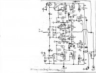
I also have built a Class G amp based on D. Self book.It was a 400 Watt amp at 8 ohms with a supply of 110-55-0-55-110 Dc.It works fine in the real world but because of the losses due to the series connection of the outputs you will get lesser power as against using a Class H topology.I used bipolar outputs.
regards mgr
MGR,
I just purchased the book by douglass self and from the UPS tracking info it will be here on Monday. Anyway I can't wait to see how he does things. Concerning your Class-G amplifier how does it sound? Do you have any sort of performance data with respect to frequency response, THD, etc? What type of output transistors did you use? In retrosepct is there anything you would do differently if you had to do it all over again?
Thanks,
Randy
- Status
- This old topic is closed. If you want to reopen this topic, contact a moderator using the "Report Post" button.
- Home
- Amplifiers
- Solid State
- Class G Bias Questions