The amplifier was called Taterka Linear, and was made from a German descendent......we have a lot of "chucrutes" here.
The amplifier interesting characteristic was that used a lot of mechanical keys, and now a days , diy people search those units to use the A to B, A to C, and all combinations to switch signals... also speakers A, B, C, Mixed, surround and inverted....mono switch...left only, rigth only....very good as a test central.
Those units were made from 1975 to 1978, and they close the doors.... was a second class amplifier, low powered, electrolitic condenser output, first and second stages used condenser coupling.... and TIP31 transistors in the output.
I have one entire power amplifier board, will try some image to show you.
For a while i am simulating, and make another one too, improoving the voltage and some circuits to more modern ideas.
It used some automatic gain control....interesting.
Also i will try to find the Panel to have some image to show you all.
As i am trying to find some "bad reference", this one can be...only 18 volts, non simetrical supply.... big miller capacitors....hehe.....all to be terrible!......maybe 4 watts in 8 ohms.
The modified unit jumped to 12 Watts with 35 volts..... the standar circuit used 18 Volts.
To the ones that are curious, and like to see old things....soon i will show you, and also will call my friends to analise, and to judge the modified unit i made.... a little bit more powerfull and more modern.... and the standard unit, and to tell how it sounds in comparison with some modern circuit...will use JLH as reference, as everybody already heard JLH circuits.
Many friends travelling, weather is turning hot here....people on vacations..... the temperature peak will be around Christmas and January., this way i will wait the guys to make the test.
But you, that like those things, be waiting the name Taterka in our forum, as i will show some images and circuits before the test be made.
regards,
Carlos
Some pictures, low resolution, made with pen cam, those cheap ones
Can give one idea.
the heat sinks are off, and two channels are over that board.
Output with 1000uf/25 volts electrolitic condenser.
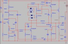
I will arrange the Simulator schematic and will publish here in a matter of 30 minutes.
Will be not the one i improve, will be the original, the factory standard circuit made in 1977 (electrolitic condensers by Siemens with the date registered on them)
regards,
Carlos
Can give one idea.
the heat sinks are off, and two channels are over that board.
Output with 1000uf/25 volts electrolitic condenser.
I will arrange the Simulator schematic and will publish here in a matter of 30 minutes.
Will be not the one i improve, will be the original, the factory standard circuit made in 1977 (electrolitic condensers by Siemens with the date registered on them)
regards,
Carlos
Attachments
 - following excavation
 Epupa, i made a threat saying Good Bye, i was going to combat
And i put some girls with bikinis and strips.
People send it to "Everything else".....or "off topic"
I will try to send you the picture without black strips.
Yeah!....Archeologist, as my people is not making the sound i like, maybe i love distortions...why not?
regards,
Carlos
And i put some girls with bikinis and strips.
People send it to "Everything else".....or "off topic"
I will try to send you the picture without black strips.
Yeah!....Archeologist, as my people is not making the sound i like, maybe i love distortions...why not?
regards,
Carlos
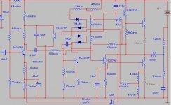
Taterka, the modified schematic i tested in Multisim
Worked very well, but i made some modifications in the drawn, to make it pretty to publish to you all.
Maybe some mistake, this is not uncommon my side.
This one is not assembled, and no one heard it, as it do not exist in real world...it is only virtual.
regards,
Carlos
Worked very well, but i made some modifications in the drawn, to make it pretty to publish to you all.
Maybe some mistake, this is not uncommon my side.
This one is not assembled, and no one heard it, as it do not exist in real world...it is only virtual.
regards,
Carlos
Attachments
- Status
- This old topic is closed. If you want to reopen this topic, contact a moderator using the "Report Post" button.
- Home
- Amplifiers
- Solid State
- Soon i will show you the Taterka, one old amplifier made in Brazil