No wonder this thread is still going strong.Amazing. The true diy spirit.
Regarding DIY spirit, (off topic warning)- my late father also had a DIY spirit which made him try his hands at building a stereo amp without knowing anything about electronics. Nor did he even have a multimeter but used a 6 volt lamp to guess at voltage drops in the circuit.
It took him quite a while, but he did finish it and it worked for many years until his son (me) took it apart to figure out what made it tick.
DIY spirit . . . don't leave home without it.
Here are the results of the building of two Zeus monoblocks.
The idea to build them on a nice wooden plywood board came
after a good friend gave me the boards, initially intended for another project that
had nothing to do with audio.
I had them cut to size with golden ratio proportions. All holes were drilled together with another friend who has a drill press.
The PCBs were also made by him. Not that I couldn't do that, but he really wanted to do it and it's always nice to involve others in a project.
Direct connections of the DAC were not possible due to the output impedance of the DAC being too high for the input transformer.
A minimalist buffer with very low output impedance solved that problem.
The PCB also contains the bias control, which only consists of a 7805, a 10k trim potentiometer and a pair of decoupling capacitors.
The input and output transformers are the Sowters.
Mosfets are IRFP240 that I had lying around.
The red and black speaker connections serve as terminals for a 0.1 Ohm resistor in series with the power supply line of the transistors to easily measure the quiescent current which is set to 400mA per mosfet and enough for me to get a reasonable heat / distortion ratio.
The Rtem is 120k with a 2.2nF in parallel and 8.2k in series.
The amplifiers sound very good to my ears.
Especially very detailed, open and musical.
The distortion is 0.14% 1kHz 1W, which is more than what Susan measures with her amplifiers but inaudible to me.
I think other mosfets might give better results.
Many thanks to everyone who helped me complete this. You know who you are...
Awesome, many thanks for posting up the pictures, tests, and information.Another view:
...
Hi @Netlist Hugo,
Yes, indeed and very fab to see all the hard work you have done over the months coming to fruition.
I haven't done much audio recently, mostly coding for the RA4M1 processor as used on the new official Arduino UNO R4 (32bit ARM M4F).
Saying that, I have done on-the-fly sine generation using Taylor Series approximation, outputting to an I2S DAC - so that is audio!

Mauve = Reference sine-wave at 440.00Hz
Green = Sine-wave at 440.00Hz with 2nd to 9th harmonics - all calculated within the 44.1kHz wordclock rate.

As previous, but with the 3rd to 9th harmonics with inharmonicity shifts as one would get from steel-strings

1 - Yellow trace = Interrupt timing
2, 3, 4 = I2S interface
I used the Renesas EK-RA4M1 dev board for this, as it has the 100pin package. The UNO R4 uses the 64pin version which doesn't have the I2S interface bought out onto the available pins.
Keeps me busy!
Yes, indeed and very fab to see all the hard work you have done over the months coming to fruition.
I haven't done much audio recently, mostly coding for the RA4M1 processor as used on the new official Arduino UNO R4 (32bit ARM M4F).
Saying that, I have done on-the-fly sine generation using Taylor Series approximation, outputting to an I2S DAC - so that is audio!
Mauve = Reference sine-wave at 440.00Hz
Green = Sine-wave at 440.00Hz with 2nd to 9th harmonics - all calculated within the 44.1kHz wordclock rate.
As previous, but with the 3rd to 9th harmonics with inharmonicity shifts as one would get from steel-strings
1 - Yellow trace = Interrupt timing
2, 3, 4 = I2S interface
I used the Renesas EK-RA4M1 dev board for this, as it has the 100pin package. The UNO R4 uses the 64pin version which doesn't have the I2S interface bought out onto the available pins.
Keeps me busy!
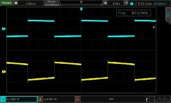
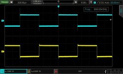
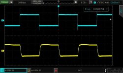
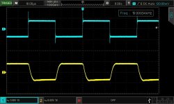
This is fab, many thanks for postingSome scope pictures, 100Hz, 1kHz, 10kHz and 20kHz.
Upper trace is generator output.
This is way above my understanding but I'm looking with awe at all the different disciplines that you master.Keeps me busy!
Hugo
Hi @Netlist Hugo,
Yes, indeed and very fab to see all the hard work you have done over the months coming to fruition.
I haven't done much audio recently, mostly coding for the RA4M1 processor as used on the new official Arduino UNO R4 (32bit ARM M4F).
Saying that, I have done on-the-fly sine generation using Taylor Series approximation, outputting to an I2S DAC - so that is audio!
View attachment 1239209
Mauve = Reference sine-wave at 440.00Hz
Green = Sine-wave at 440.00Hz with 2nd to 9th harmonics - all calculated within the 44.1kHz wordclock rate.
View attachment 1239211
As previous, but with the 3rd to 9th harmonics with inharmonicity shifts as one would get from steel-strings
View attachment 1239212
1 - Yellow trace = Interrupt timing
2, 3, 4 = I2S interface
I used the Renesas EK-RA4M1 dev board for this, as it has the 100pin package. The UNO R4 uses the 64pin version which doesn't have the I2S interface bought out onto the available pins.
Keeps me busy!
Why does the interrupt ( trace 1 ) follow the I2S interface (trace 2)?
Thanks.
The machine size qoes up rapidly with the size of core and weight of wire one wants to wind.
If I can't wind bifilar it isn't any good as my transformers need the same lengths of wire to be balanced and matched.
I may do something - but it is a lot of work to make something like this - and I do have access to a lathe and a milling machine!
Just looking at the video made me tired.... it looks like it requires quite a shop.... how about replacing a lot of that work with a 3D printer?
Also, the way the PCB assembly (case and processor board) were installed were not optimal at all.
What type of mini table top saw was that?
What kind of material/board was he using to as backing board when drilling holes into material? The metal clasp...
Because the I2S interface is buffered, so it is calculating the next sine values to put into a FIFO stack that will automatically get loaded into the data bit shift-register as needed to give uninterrupted data clocking.Why does the interrupt ( trace 1 ) follow the I2S interface (trace 2)?
The FIFO is ready to accept new L/R data once that transfer takes place, so it looks behind; as it is in fact so by one or more values (depending on the FIFO depth selected).
See section 33.3 page 1018 for a block-diagram.
https://www.renesas.com/us/en/document/dst/ra4m1-group-datasheet?r=1054146
As to how one puts things together, these are some of my setups:

Line-driver for centre and bass amps in our 5.1 setup - runs off a single +24V supply:

The bass-amp for the 5.1 system.

My test baseboard with a fixed dual-section quad-filar output-transformer and heatsink setup.

Another variation.

Line-driver for centre and bass amps in our 5.1 setup - runs off a single +24V supply:
The bass-amp for the 5.1 system.
My test baseboard with a fixed dual-section quad-filar output-transformer and heatsink setup.
Another variation.
Depending, my line-drivers are running on+24V (even the 6SN7 / 7N7 tune one) and the power amplifiers on something between 34 and 48 volts.... A quick one Susan on the design. Are the mosfets running HT of 150volts like tube amps? Whats the bias current? Whats the step down transformer ratio. 3:1? Whats the input transformer ratio 1:75?
The power stages are biased about 0.75 amps per MOSFET in PP and 2 or so amperes in Single Ended.
Power stage input is 1 to 5+5 (for PP), and the output is normally recommended to be 2:1 ratio between primary and secondary windings (but can vary depending on the load it is driving). I.e. with the correct ratio transformer my amps can directly drive a ribbon-speaker.
- Home
- Amplifiers
- Solid State
- Zero Feedback Impedance Amplifiers


