Dear Susan, Dear John,
thanks a lot for your responeses about the RF amp. It's just a quick idea the same as using a lot of OPs and parallel them. I know the RF design is completely different from power amp design. But 40MHz and about 2MHz what I got with the fastest designs developed for audio seems not so far away.
On topic - Susan you really ashamed me. When I started 25 years ago building amps first I learned is to use feedback. Well that had some tradeoffs I build more oscillators than amps. Another 10 years later - my amps are more stable that time - I read, that a lot feedback will cause some audible problems. So I removed feedback with the effect of more complex circuits. I also build some tube amps, no power but headphone and preamp. Yes they are looking very nice, that glowing is really impressive. And that gave me the inspiration to make semiconductor amps better. Well, some power regulation / stabilisation here some CCS over there, I think my latest designs are not much more simple than that commercial stuff (I repaired a lot of them in the past years!)
And now you came with a two transistor design, added two transformer in the in- and output. Just like that golden time where transistors cost more than transformers. And you tell me it sounds good. Shall I really believe this? As well as tube amps they are all from an ancient time. Cum on we're living in a time of highly integrated semiconductor chips, computers, where billions of transistors are in and connected in a very complex manner, this cannot be true. Why we need then the use of the other billion transistors? They cannot be out of job!
Using some high quality parts, the less as possible in the signal path and made it in the RIGHT other way round. Susan - your design is really cool.
Susan,
On the other hand, while I am sitting here listening to Norah Jones through my Nemisis monoblocks, I wonder why one would need per channel no less than 2 transformers and two transistors, when half of that would be perfectly adequate...
But, Susan, seriously, are you familiar with the Nemesis? Do you hasve an opinion on how your amp would compare to that, soundwise?
Jan Didden
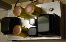
Attachments

Wahey! Only just read this thread. I love that topology Susan! My present single-ended amp is in the same spirit but uses a single 801A valve in each channel with a Lundahl amorphous core stepup on the input as driver. Works a treat and everybody who hears it wants me to build them one. Need sensitive speaks though
Semper Musica!
Semper Simplistica!
Brian.
Semper Musica!
Semper Simplistica!
Brian.
Hi everyone,
Many thanks for your continued interest.
I have reasembled my test setup to be able to make some of the measurments requested and incorporated this in updates to my amplifier web page:
http://www.susan-parker.co.uk/zeus.htm
which now have links to two transformer spec pages.
Some highlights...
Input impedance = nominal 150 ohms parallel and 600 ohms series wiring of primarys.
Termination resistance is 120 k ohm.
Output impedance is 2.78 ohms at 1 kHz.
Laminations are 0.35 mm thick.
There is also inductance etc. for those happy bunnies who can make working Spice transformer models. Of course one also needs working mosfet models, but that is another thread.
Best wishes,
Susan.
Hi Graham.
Thank you for your appreciation. And over a decade in time, sigh.
Guess I will have to put some bits together and send you a parcel. I assume you have power supplies n' stuff.
Input transformer input impedance at 1 kHz:
Parallel = 165 Ω.
Series = 667 Ω.
I normally use parallel mode whcih gives me a 1:10. Series is 1:5.
As you have probably noticed my amplifer is a power stage, and does require a seperate driver after the attenuator section.
This is a different split from normal but based on technical reason not some glitzy marketing speil.
The windings of my output transformer is different and doesn't model the same, however I would like to use better materials. If I ask Sowter to make a pair I guess I will get properly grain orientated laminations?
I also want to try using some mu-metal interleaving.
With quad filar winding the coupling is very good, far better than a conventional winding topology. There will be some loss but I am not sure exactly how much. I would have to try out this alternative but overall I prefer the seperate output windings as this gives more flexability in load matching.
2.78 ohm at 1 kHz.
I set for reasonable disapation. There is some change as the bias kicks in.
I have some test gear (including an HP Audio Analyser) but need to sort out and match some power devices - plus the time to do this as I have some short term work pressures.
I think that the output distorsion levels are such that it is subserviant to the speaker driver/crossover distorsions. The ultimate distorsion after all being the combination of the two, which is why I believe valve level distorsion whilst "awful" on paper often don't sound as bad as one could expect.
I understand the 100 W - 8 ohms but in my experience I rarely use more than 5 W or so except for daytime classical listening (the loud bits).
A lot depends on the speaker sensitivity.
I don't beleive that it is possible to completly remove the loudspeaker's reactive and frequency effects on the feedback network of the amplifier. It can be minimised for a certain range of conditions and tuned to a preference, but it will always be there.
The only wayI see to make a feedback amplifer work without artifact is to have two output stages, one with a non inductive load of say 12 ohms (or whatever would be a good overall match to the nominal loudspeaker impedance) and used for the amplifier feedback, and the second slaved but WITHOUT any feedback connection which is used to drive the loudspeaker.
Obvioulsy the output devices have to be matched and closely mounted on a "nice big heatsink".
As to my transformer design - it's a third type, neither valve or solid state, and doesn't to my ear have the same sound as either. Personally what I hear most is the quality of the source material rather than a "valve" or "solid state" sound.
But one becomes used to what one listens to, which I would agree doesn't mean the same as better (or worse for that matter).
Perfectly appreciated.
I was looking at the Jordan full range drivers - which I use in my marble spheres - but they are a bit bright at the top end with my amplifiers.
I am thinking about other drivers - more conventional but less expensive.
Many thanks for your time and interest.
Best wishes,
Susan.
P.S.
Sorry it's late now, I will have to reply to other posts tomorrow.
Graham Maynard said:Hi Susan,
What's inside your amp?
In your case that really is a redundant question; but oh how much thinking you must already have done about so little !!!
Thank you for your appreciation. And over a decade in time, sigh.
I'm moving over to your thread here, and I note that there already are some worthy contributions. I'd love to hear your amp, but alas I live north of Belfast so it is not likely I can call round for a demo.
Guess I will have to put some bits together and send you a parcel. I assume you have power supplies n' stuff.
In jcx's other thread I suggested that your input transformer would need to be something rather special, I was thinking of a need for about 1:20+20 of grain orientation + split windings. I see you have described it as 1;5+5, which allows you to use bell wire for the input cable. However, I think figure-8 pairing has a natural impedance closer to 100 rather than 600 ohms, though 600 ohm driving should not have too great an effect at audio frequencies if the cable is only of 'domestic' length. If signal source push-pull/balanced driven at say series 56 ohms per core wrt to ground, the cable should have an unchallengable hf phase response, and could be loaded with a resistive portion across the transformer primary as well as secondary. ( I wrote this yesterday and see that Hugh too has come up with lower impedance and higher ratio, maybe there is room for more investigation here.)
Input transformer input impedance at 1 kHz:
Parallel = 165 Ω.
Series = 667 Ω.
I normally use parallel mode whcih gives me a 1:10. Series is 1:5.
As you have probably noticed my amplifer is a power stage, and does require a seperate driver after the attenuator section.
This is a different split from normal but based on technical reason not some glitzy marketing speil.
I have no wish to upset or dampen your enthusiasm, but as with PMA I too would wonder about phase accuracy, because an amplifier can sound good enough for listening satisfaction (and easily better a Quad set-up) without it being as accurate as is possible with other designs that are equally capable of resolving swaying or breathing musicians. You mention a 300kHz bandwidth; is this -3dB, and did you ever run an audio frequency phase check ? I suspect transformer core losses, which become both measurable and so audible when you A/B compare mains types pressed into audio usage when compared with properly grain orientated versions.
The windings of my output transformer is different and doesn't model the same, however I would like to use better materials. If I ask Sowter to make a pair I guess I will get properly grain orientated laminations?
I also want to try using some mu-metal interleaving.
With regard to driving the loudspeakers directly from source + c.t. transformer connections used as a choke I recon that per half hf voltage due to loss of coupling between halves and per half inductance might be theorectically less natural than via your separate core coupled winding, but it would be worth auditioning in case it fortuitously compensates for transformer imperfections.
With quad filar winding the coupling is very good, far better than a conventional winding topology. There will be some loss but I am not sure exactly how much. I would have to try out this alternative but overall I prefer the seperate output windings as this gives more flexability in load matching.
Did you ever measure the output resistance/impedance at say 1kHz ? Have you managed to achieve a decent loudspeaker damping figure without NFB ? Have you tried listening whilst adjusting the quiescent bias and found a level at which further increase does not improve reproduction, or did you set for a reasonable dissipation ? Have you ever subjected the amplifier to distortion test set measurement ?
2.78 ohm at 1 kHz.
I set for reasonable disapation. There is some change as the bias kicks in.
I have some test gear (including an HP Audio Analyser) but need to sort out and match some power devices - plus the time to do this as I have some short term work pressures.
Like johnnyx I could ask myself if I need to change direction, as inded I have already have following Pavel's new circuit release, but as I prefer transformerless power, regard 100W-8 ohms a requirement, and as it is possible to minimise feedback induced problems, then I would need to know phase, distortion and output impedance figures of your design before I could be convinced. I would rather have an accurate feedback amplifier and then pre-amp modify its signal for listening that suits my ears, than have an amplifier that is easy to listen to but which compromises waveform accuracy in a way that can never be subsequently adjusted out.
I think that the output distorsion levels are such that it is subserviant to the speaker driver/crossover distorsions. The ultimate distorsion after all being the combination of the two, which is why I believe valve level distorsion whilst "awful" on paper often don't sound as bad as one could expect.
I understand the 100 W - 8 ohms but in my experience I rarely use more than 5 W or so except for daytime classical listening (the loud bits).
A lot depends on the speaker sensitivity.
I don't beleive that it is possible to completly remove the loudspeaker's reactive and frequency effects on the feedback network of the amplifier. It can be minimised for a certain range of conditions and tuned to a preference, but it will always be there.
The only wayI see to make a feedback amplifer work without artifact is to have two output stages, one with a non inductive load of say 12 ohms (or whatever would be a good overall match to the nominal loudspeaker impedance) and used for the amplifier feedback, and the second slaved but WITHOUT any feedback connection which is used to drive the loudspeaker.
Obvioulsy the output devices have to be matched and closely mounted on a "nice big heatsink".
As to my transformer design - it's a third type, neither valve or solid state, and doesn't to my ear have the same sound as either. Personally what I hear most is the quality of the source material rather than a "valve" or "solid state" sound.
But one becomes used to what one listens to, which I would agree doesn't mean the same as better (or worse for that matter).
I must state that I have not heard this kind of amplifier, and so I cannot state whether it is cleaner sounding than a feedback amplifier or not, so please do not take my points as being either an attempt to be definitive or derogatory.
Perfectly appreciated.
You like the Line Source too ! What is your driver ? Mine is Visaton FRS-8, far from perfect, but cheap and clean over mid range and needs a central top end tweeter, though I'm always on the lookout for other suggestions.
I was looking at the Jordan full range drivers - which I use in my marble spheres - but they are a bit bright at the top end with my amplifiers.
I am thinking about other drivers - more conventional but less expensive.
Many thanks for your time and interest.
Best wishes,
Susan.
P.S.
Sorry it's late now, I will have to reply to other posts tomorrow.
nemesis
http://www.stereophile.com/amplificationreviews/740/index6.html
Speaking of single-ended amplifiers, it's worth noting the work of Paris-based Jean Hiraga at L'Audiophile over 10 years ago. He developed a single-ended, transformer-coupled transistor power amplifier called Nemesis, with no other active devices whatsoever other than a single power device (namely a 25SK 135 power FET). The Nemesis's utter simplicity helped it achieve a sound that closely approached that of a classic WE 300B single-ended triode amplifier.—Martin Colloms
Audiophile n°34, janvier 1985
Audiophile n°35, printemps 1985
Re: nemesis
Hi Dimitri,
Thank you for the reference...
... which makes interesting reading.
However the Nemesis is a valve design with the power fet instead of a tube, and the gain stage is the FET transfer characteristics, which as Eva has pointed out are a bit shakey.
These single ended designs by their nature have an ASYMETRIC output impedance, which will affect the reproduced sound quality. They can only drive in one direction, the other direction is dictated by the back EMF of the transformer or by the current sink.
Again this is not necessarily good or bad, it's just how it is.
My amplifier uses an impedance gain stage, which does not add any noise. It is literally "wire with gain". To do this voltage amplification I trade off a low impedance input for a high impedance output.
Of course, as has been pointed out by several people, transformers are not linear in the same way as a feedback loop amplifier. But then I am not aiming for 0.0001% THD into a non-inductive 8 ohm resistor - because listening to a resistor is very boring!
My amplifier is push-pull off a single supply rail which gives a number of advantages.
1. Very high supply ripple rejection - small (i.e. cheep) smoothing cap.
2. Active drive in both directions at all times - constant impedance.
3. Low quiescent bias - circa 500 to 600 mA - less heat.
... but I am beginning to repeat myself, which is also boring.
Sufficient to say I am not trying to reproduce a Triode sound (nor a solid state sound for that matter). I am trying to reproduce the sound encoded in the original recording - no more, no less.
It should be remembered that the average signal for a classical CD with large peaks is only around 12 bits resolution, i.e. 1 in 4096, which is 0.025% distorsion before one even starts with anything else like the woefully inadequate sampling rate of 44 kHz.
I know this because I built my own CD player using a CD-ROM drive and striped out the digital audio data from the signal processing chip to feed into my own Burr Brown DACs to then drive my amps directly.
All this oversamplig filter stuff is a fudge, and introduces it's own signature to the sound. It can be a very good fudge, and be more pleasant to listen to, but that doesn't negate the fact that it is modifying the original sound.
Any item that can be interchanged with another of similar function and that results in a different sound will be doing this, with the one exception of the single item in the group that isn't modifying the sound. But that one probably won't be recognised as such, given that each will be subtly (or not so subtly) different anyway.
So at the end of the day it comes down to personal choise and preferance (and spelling) and what works best for one person isn't necessarily going to be good for another.
Best wishes,
Susan.
Hi Dimitri,
Thank you for the reference...
dimitri said:http://www.stereophile.com/amplificationreviews/740/index6.html
Speaking of single-ended amplifiers, it's worth noting the work of Paris-based Jean Hiraga at L'Audiophile over 10 years ago. He developed a single-ended, transformer-coupled transistor power amplifier called Nemesis, with no other active devices whatsoever other than a single power device (namely a 25SK 135 power FET). The Nemesis's utter simplicity helped it achieve a sound that closely approached that of a classic WE 300B single-ended triode amplifier.—Martin Colloms
Audiophile n°34, janvier 1985
Audiophile n°35, printemps 1985
... which makes interesting reading.
However the Nemesis is a valve design with the power fet instead of a tube, and the gain stage is the FET transfer characteristics, which as Eva has pointed out are a bit shakey.
These single ended designs by their nature have an ASYMETRIC output impedance, which will affect the reproduced sound quality. They can only drive in one direction, the other direction is dictated by the back EMF of the transformer or by the current sink.
Again this is not necessarily good or bad, it's just how it is.
My amplifier uses an impedance gain stage, which does not add any noise. It is literally "wire with gain". To do this voltage amplification I trade off a low impedance input for a high impedance output.
Of course, as has been pointed out by several people, transformers are not linear in the same way as a feedback loop amplifier. But then I am not aiming for 0.0001% THD into a non-inductive 8 ohm resistor - because listening to a resistor is very boring!
My amplifier is push-pull off a single supply rail which gives a number of advantages.
1. Very high supply ripple rejection - small (i.e. cheep) smoothing cap.
2. Active drive in both directions at all times - constant impedance.
3. Low quiescent bias - circa 500 to 600 mA - less heat.
... but I am beginning to repeat myself, which is also boring.
Sufficient to say I am not trying to reproduce a Triode sound (nor a solid state sound for that matter). I am trying to reproduce the sound encoded in the original recording - no more, no less.
It should be remembered that the average signal for a classical CD with large peaks is only around 12 bits resolution, i.e. 1 in 4096, which is 0.025% distorsion before one even starts with anything else like the woefully inadequate sampling rate of 44 kHz.
I know this because I built my own CD player using a CD-ROM drive and striped out the digital audio data from the signal processing chip to feed into my own Burr Brown DACs to then drive my amps directly.
All this oversamplig filter stuff is a fudge, and introduces it's own signature to the sound. It can be a very good fudge, and be more pleasant to listen to, but that doesn't negate the fact that it is modifying the original sound.
Any item that can be interchanged with another of similar function and that results in a different sound will be doing this, with the one exception of the single item in the group that isn't modifying the sound. But that one probably won't be recognised as such, given that each will be subtly (or not so subtly) different anyway.
So at the end of the day it comes down to personal choise and preferance (and spelling) and what works best for one person isn't necessarily going to be good for another.
Best wishes,
Susan.
I happen to own the schematic from the Bajazzo and scanned the relevant part for your interest and pleasure.john curl said:This design is almost exactly the circuit with germanium transistors that I have in my almost 40 year old Telefunken Bajazzo portable radio.
Note the details about voltage and current supplied in those days.
If anyone wants the whole schematic, mail me. It's only a few pages.
I found another Telefunken portable tape deck that uses this topology: the M300 /M302
/Hugo
Attachments
Re: Re: Only one suggestion
Hi Patrick,
Thank you for the positive comments.
... and everyone else who expressed an interest in buying.
I can only get at most 10% discount from Sowter and that would not cover the cost of repackaging and reposting to people. Also I am not set up to take CC payments, etc.
The tricky (relativly) part to make is the input transformer, as it needs to be exactly matched for number of turns in each section and as this has lots of turns with fine wire it is difficult to do without a proper coil winding setup. Plus it needs the right laminations etc.
So I would recoment buying directly from Sowter for anyone who is really interested in building this design.
http://www.sowter.co.uk/
Unfortunantly they are about UKP 40 a go, plus VAT and postage, so I hesitate to be too enthusiastic because I would not want anyone to feel that I had "done a dirty" on them if they are unhapy with the results acheived.
Also with Sowter one could order the special lamination mix that they are using for some of the attenuator transformers - although I can't comment on the exact resuits as I haven't bench tested any.
As to the output transformers, they can be made from good quality mains transformer kits - just ensure that the laminations are M6 type not "pig iron".
I can ask Sowter to quote for ready made, but these are something that you might want to experiment with in terms of windings, size and turns. They are probably going to be quite expensive as well, given the weight of laminations (which are charged for by the kilo).
These would probably be around the UKP 100 each mark, plus VAT and shipping. A 200 VA transformer kit from RS is UKP40, although I don't know what lamination material is used for this. (I note that these type of kits are not as readily available as they used to be.)
Please remember though that the output transformers are special and MUST be made with multi-filar windings. They are NOT the same as standard valve output transformers, so don't let anyone try to convince you that my winding topography is wrong as the resultant output transformer if made with sectioned windings WILL NOT WORK!
I have measured the inductance between the primary and the secondary of the output transformer and my LCR meter tells me that this is:
1.95 H @ 1 kHz
148 H @ 120 Hz
Whether this is meaningfulI don't know.
I hope the above helps.
===========
Hi Dave,
Thank you also for the positive comments.
I should point out that I have deliberatly split the amplification stages differently to normal, and in this regard it is closer to RF practise.
The final power stage - i.e. my amplifier - is designed to sit next to the load - i.e. the speaker - it is driving.
The pre-driver stage is at the source/pre-amp end (and could be part of it) which drives the ballenced line XXX yards to the power amp.
This split provides the optimum signal conditions with isolated differential ballenced line drive that is immune to interferance and ground loops, and a short high current path to the loudspeaker.
Obviously one can put it all together in one box. However it becomes very heavy with all the transformers - particually for a 6:2 surround system!
Good perceived value though!
--------------
Best wishes,
Susan.
Hi Patrick,
Thank you for the positive comments.
EUVL said:Susan,
I have only one suggestion to make :
I agree totally with you that the only way to assess a design is to build and listen. So to put the other guys to task who says no before trying, may I suggest you make some enquiries with your suppliers and offer us a set of transformers at a reasonable price (whatever that means).
I guess if it is not too unaffordable, you would not have too much difficulty finding enough 'customers' for a batch of 10 or even 20, which helps to keep cost down.
Once there is feedback from different corners, the sceptics would shut up.
Me, I am not qualified to comment. I have not built one. But I also do not rule out that it can sound pleasant. It is an interesting design in any case, and the audio world is definitely a not a poorer place with it.
Patrick
... and everyone else who expressed an interest in buying.
I can only get at most 10% discount from Sowter and that would not cover the cost of repackaging and reposting to people. Also I am not set up to take CC payments, etc.
The tricky (relativly) part to make is the input transformer, as it needs to be exactly matched for number of turns in each section and as this has lots of turns with fine wire it is difficult to do without a proper coil winding setup. Plus it needs the right laminations etc.
So I would recoment buying directly from Sowter for anyone who is really interested in building this design.
http://www.sowter.co.uk/
Unfortunantly they are about UKP 40 a go, plus VAT and postage, so I hesitate to be too enthusiastic because I would not want anyone to feel that I had "done a dirty" on them if they are unhapy with the results acheived.
Also with Sowter one could order the special lamination mix that they are using for some of the attenuator transformers - although I can't comment on the exact resuits as I haven't bench tested any.
As to the output transformers, they can be made from good quality mains transformer kits - just ensure that the laminations are M6 type not "pig iron".
I can ask Sowter to quote for ready made, but these are something that you might want to experiment with in terms of windings, size and turns. They are probably going to be quite expensive as well, given the weight of laminations (which are charged for by the kilo).
These would probably be around the UKP 100 each mark, plus VAT and shipping. A 200 VA transformer kit from RS is UKP40, although I don't know what lamination material is used for this. (I note that these type of kits are not as readily available as they used to be.)
Please remember though that the output transformers are special and MUST be made with multi-filar windings. They are NOT the same as standard valve output transformers, so don't let anyone try to convince you that my winding topography is wrong as the resultant output transformer if made with sectioned windings WILL NOT WORK!
I have measured the inductance between the primary and the secondary of the output transformer and my LCR meter tells me that this is:
1.95 H @ 1 kHz
148 H @ 120 Hz
Whether this is meaningfulI don't know.
I hope the above helps.
===========
Hi Dave,
planet10 said:Susan,
A very elegant design... a refreshing idea...
I too was thinking group buy as i read thru this thread...
and some concrete ideas on matching the input requirements with stuff more typically found lying around.
dave
Thank you also for the positive comments.
I should point out that I have deliberatly split the amplification stages differently to normal, and in this regard it is closer to RF practise.
The final power stage - i.e. my amplifier - is designed to sit next to the load - i.e. the speaker - it is driving.
The pre-driver stage is at the source/pre-amp end (and could be part of it) which drives the ballenced line XXX yards to the power amp.
This split provides the optimum signal conditions with isolated differential ballenced line drive that is immune to interferance and ground loops, and a short high current path to the loudspeaker.
Obviously one can put it all together in one box. However it becomes very heavy with all the transformers - particually for a 6:2 surround system!
Good perceived value though!
--------------
Best wishes,
Susan.
Netlist said:
I happen to own the schematic from the Bajazzo and scanned the relevant part for your interest and pleasure.
Note the details about voltage and current supplied in those days.
If anyone wants the whole schematic, mail me. It's only a few pages.
I found another Telefunken portable tape deck that uses this topology: the M300 /M302
/Hugo
Hi Hugo,
Thank you for the reference.
However, despite the way they are drawn, the AD155s are PNP transistors and are therefor operating as amplifiers, not followers.
AD155 PNP UcE:15V PT:6.0W C-2D3 SOT-9 AF Output Stage
The input transformer Tr 401 is something like 3.5:1+1 or 2:1+1 step down impedance matching and the output transformer Tr 402 is probably also a step down about 2+2:1 (ish) to match the speaker impedance.
Therefor this circuit is not the same as my amplifier - although this is the topography used in many RF power amplifiers.
I also have similar designs in my Mullard Reference Manual of Transistor Circuits - First edition 1960.
However many thanks to those who have spent time and effort looking up these references, it is all much appreciated.
Best wishes,
Susan.
Susan,
You never expected this overwhelming positive response didn’t you?
Thanks for the technical info, I believed John Curl when he said he recognized the same design.
So this means your design would be unique.
I can’t wait to build it. It’s on the list of future projects.
/Hugo
You never expected this overwhelming positive response didn’t you?
Thanks for the technical info, I believed John Curl when he said he recognized the same design.
So this means your design would be unique.
I can’t wait to build it. It’s on the list of future projects.
You should start a new thread on this one too, it’s enlightening to read your posts.Susan-Parker said:I know this because I built my own CD player using a CD-ROM drive and striped out the digital audio data from the signal processing chip to feed into my own Burr Brown DACs to then drive my amps directly.
Don’t worry about repeating yourself, we have a tradition here to fabricate monster threads.Susan-Parker said:... but I am beginning to repeat myself, which is also boring. [/B]
/Hugo
Hi everyone,
Just for your information this is why I built my power amplifiers:
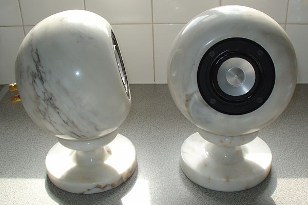
http://www.susan-parker.co.uk/susan-speaker-sphere.htm
and I designed these because I wasn't happy with the sound of my LS3/5As (or the alternatives).
The page text is a bit promotional as I was trying to commercialize the design, but with as much success as with my power amplifiers - i.e. NONE.
Also why I am not trying for 100 Watts! I have a separate bass speaker for that - which amongst other reasons is to minimize the Doppler effects.
Many thanks for everyone's positive comments and encouragements.
Best wishes,
Susan.
Just for your information this is why I built my power amplifiers:
http://www.susan-parker.co.uk/susan-speaker-sphere.htm
and I designed these because I wasn't happy with the sound of my LS3/5As (or the alternatives).
The page text is a bit promotional as I was trying to commercialize the design, but with as much success as with my power amplifiers - i.e. NONE.
Also why I am not trying for 100 Watts! I have a separate bass speaker for that - which amongst other reasons is to minimize the Doppler effects.
Many thanks for everyone's positive comments and encouragements.
Best wishes,
Susan.
Snowball on tent
Doesn't this depend frome the driver too? Note that Susan seems to use line array speakers, each driver being 2".
Maybe splitting bass (driven with SS amp) and the rest would be a solution? But then throwing away the required phase coherence due to the required HP filter?
Tino
Upupa Epops said:Whatabout damping factor, Susan ? Do you think, that several ohms is good ? By this value is bass like snowball throwed on tent
Doesn't this depend frome the driver too? Note that Susan seems to use line array speakers, each driver being 2".
Maybe splitting bass (driven with SS amp) and the rest would be a solution? But then throwing away the required phase coherence due to the required HP filter?
Tino
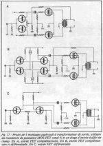
Re: other push-pull projects
Hi Dimitri,
Thank you for the schematics.
I note the following.
1. Uses negative feedback.
2. Has capacitors in the audio path.
3. Uses MOSFETs as amplifiers.
Remember that a transformer couples ALL ways, so load effects not only get fed back round on the feedback to the phase splitter, but also directly into the mosfets themselves. Wibble, wobble!
The Hiraga circuits with mosfet amplification in the final stage (without the feedback) in RF power amplifiers can self destruct if fed into a mis-matched load.
In my amplifier design using followers the mosfets have a gain of just below unity. This is a "good thing" in my book.
It is therefor very tolerant of miss matched loads - which is why I was looking to use it as a wide band RF amplifier for driving CDN units for EMC/RFI compliance testing as the resultant load is anything but a nice stable 50 ohms.
Many thanks for the time digging these schematic out for me, these are all of interest even if not the way I am doing things.
Best wishes,
Susan.
Hi Dimitri,
Thank you for the schematics.
dimitri said:push-pull projects by J.Hiraga
I note the following.
1. Uses negative feedback.
2. Has capacitors in the audio path.
3. Uses MOSFETs as amplifiers.
Remember that a transformer couples ALL ways, so load effects not only get fed back round on the feedback to the phase splitter, but also directly into the mosfets themselves. Wibble, wobble!
The Hiraga circuits with mosfet amplification in the final stage (without the feedback) in RF power amplifiers can self destruct if fed into a mis-matched load.
In my amplifier design using followers the mosfets have a gain of just below unity. This is a "good thing" in my book.
It is therefor very tolerant of miss matched loads - which is why I was looking to use it as a wide band RF amplifier for driving CDN units for EMC/RFI compliance testing as the resultant load is anything but a nice stable 50 ohms.
Many thanks for the time digging these schematic out for me, these are all of interest even if not the way I am doing things.
Best wishes,
Susan.
Speakers.
Hi Susan,
These are one of the cutest (little) speakers I've seen in my audiophile life. WOW!!!
Audiofanatic
Susan-Parker said:Hi everyone,
Just for your information this is why I built my power amplifiers:

http://www.susan-parker.co.uk/susan-speaker-sphere.htm
and I designed these because I wasn't happy with the sound of my LS3/5As (or the alternatives).
The page text is a bit promotional as I was trying to commercialize the design, but with as much success as with my power amplifiers - i.e. NONE.
Also why I am not trying for 100 Watts! I have a separate bass speaker for that - which amongst other reasons is to minimize the Doppler effects.
Many thanks for everyone's positive comments and encouragements.
Best wishes,
Susan.
Hi Susan,
These are one of the cutest (little) speakers I've seen in my audiophile life. WOW!!!
Audiofanatic
- Home
- Amplifiers
- Solid State
- Zero Feedback Impedance Amplifiers