Hi
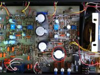
I've done some investigations and finally found a faulty cap, the one within red circle.
When I touch it while playing the hum appears, so I think it needs to be replaced.
I haven't check his solder pads, but replacing after more than 30 years seems to be a good idea.
Do you have some refs to suggest me ?
The original value is 4700uF/80V & the other upper pair is 10000uF/35V rated.
Regards
Phil
Attachments
Phil,
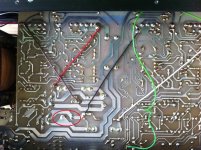
I find it highly doubtful a capacitor of this type could create the problem you are describing. A bad solder joint is more likely to be the cause.
Replacing the capacitors would definitely be a good idea since it looks like none of them have ever been replaced. I usually use ECO-S2AP472DA and ECO-SH1A103DA for the large ones. Do not forget the small ones as they need attention too. Look at the capacitor between the two right side blue trimmers. The external jacket shrunk because it has been exposed to too much heat. I am pretty sure the other capacitor beside the relay is compromised too has they usually are the first one's to die. Be sure to verify the one just between the twisted brown and red wire, my memory tells me this one too should be replaced. All the other ones should not be in too bad a shape but if you have the time and patience, you should verify them all. If you have a constant low level hum, it is a sign that some of them lost much of their capacity.
Regards,
Michel
Replacing caps
Hi Phil,
If you decide to replace the caps on the A28, as I did with great results for sound quality , then the pdf's listed below may help (the information in italics was copied from another thread). Note that the Elna replacement caps were generally larger than the originals but they all fit within the cabinet. I would not have purchased the Nichicons as they measured significantly lower than nominal. Use those recommended by Michel.
The link to the other thread is given in a post of mine earlier in this thread.
The cap list for the replacements I used in the Sugden A28 is is available here:
home.exetel.com.au/justlucky/SugdenA28/Sugden_A28_Cap_replacement_list.pdf
Also indicated are the voltage ratings and dimensions for the original caps along with some of the markings.
There is no indication in the list as to the cap function. If you need that information I loaded the circuit diagram and pcb layout to here:
home.exetel.com.au/justlucky/SugdenA28/Sugden_A28_circuit.pdf
home.exetel.com.au/justlucky/SugdenA28/Sugden_A28_PCB_layout.pdf
These were kindly made available by Michel as gif's and I've turned them into PDF's.
Hi Michel & DennyG
Your'e absolutely right Michel : bad solder join confirmed, trouble solved, no more hum.
As shown on first pic, one 4700uF/80V was concerned, checked the others big cans : Ok.
Then checked DC output and noticed it to be low enough to fire the amp.
Works fine BUT only on Left chanel, Right one is mute or plays at very very very low level.
More to investigate... but where to start from ?
I like Pana TSUP series, good quality caps at budget price.
Michel stated 100V vs 80V, sounds to be a wise advice.
I'll replace all the caps, more than 30 years of duty is a very good lifecycle")
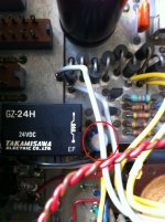
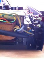
Second pic shows the relay cap to be replaced.
This one is 10uF/100V rated. Unusual value to me.
Thanks DennyG for your informations, great work done
I'll have a carefull look at your caps cookbook before my next order !
Many thanks for your attention, share, advices and kindness.
Your'e absolutely right Michel : bad solder join confirmed, trouble solved, no more hum.
As shown on first pic, one 4700uF/80V was concerned, checked the others big cans : Ok.
Then checked DC output and noticed it to be low enough to fire the amp.
Works fine BUT only on Left chanel, Right one is mute or plays at very very very low level.
More to investigate... but where to start from ?
I like Pana TSUP series, good quality caps at budget price.
Michel stated 100V vs 80V, sounds to be a wise advice.
I'll replace all the caps, more than 30 years of duty is a very good lifecycle
Second pic shows the relay cap to be replaced.
This one is 10uF/100V rated. Unusual value to me.
Thanks DennyG for your informations, great work done
I'll have a carefull look at your caps cookbook before my next order !
Many thanks for your attention, share, advices and kindness.
Attachments
Last edited:
Phil,
Glad to hear you found your bad solder joint and that the hum is gone.
Now for the low level signal on the right channel, the first things I suggest you do are:
Try playing the amp at high volume to see if it changes anything
Try tapping on the relay while the music is playing
Cycle repeatedly the speaker/headphone switch (if there is one)
Cycle repeatedly a 1/4" jack in the headphone plug (if no speaker/headphone switch)
Cycle repeatedly the front panel switches
All those tests are much easier to perform with a high frequency tone (±5 kHz) while an oscilloscope monitors the output signals of the amplifier, if you have access to this equipment.
Let me know the results and if unsuccessful we'll advance from there.
Michel
Hi Michel
Right Level signal fixed : bad solder on speaker connector...
I've to check all the front/rear panel connexions.
No more hum, the amp sounds dead quiet
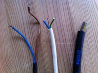
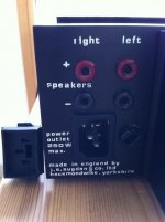
I've replaced the guenuine "poor" power cord and added an IEC socket.
First pic : left/middle = old wires - right = new copper wire
Second : IEC replaced, fits fine.
Third : detail of IEC with X2/Y2 caps and Earth coil.
I've found a freeware for frequency testing : Logiciel Tone Generator - Générateur de tonalités de test et de fréquences sonores
I've unbolted and cleaned power transistor/pads and replace thermal paste (both sides, artic silver 5).
I've noticed before this operation that right side of the haetsink was warm, bad contact.
Now temp is correct for all the transistor on both heatsinks.
More to come with caps replacement, hope it will be soon.
Regards
Phil
Right Level signal fixed : bad solder on speaker connector...
I've to check all the front/rear panel connexions.
No more hum, the amp sounds dead quiet
I've replaced the guenuine "poor" power cord and added an IEC socket.
First pic : left/middle = old wires - right = new copper wire
Second : IEC replaced, fits fine.
Third : detail of IEC with X2/Y2 caps and Earth coil.
I've found a freeware for frequency testing : Logiciel Tone Generator - Générateur de tonalités de test et de fréquences sonores
I've unbolted and cleaned power transistor/pads and replace thermal paste (both sides, artic silver 5).
I've noticed before this operation that right side of the haetsink was warm, bad contact.
Now temp is correct for all the transistor on both heatsinks.
More to come with caps replacement, hope it will be soon.
Regards
Phil
Attachments
Last edited:
Hi Gentleman.
I just got me an old A48iii - that has some problems. Left channel sounds really bad when turning up the volume above 9 o’clock and right channel blows the fuse. I was trying to adjust the bias and midpoint voltage for left channel – but became unsure – where do you measure the midpoint voltage? And what is the reference?
Regards, Michael.
Hi Michael,
You should never try to adjust biases and midpoints on a defective amplifier.
This should only be done when you know the amplifier is working properly.
The bias should be set to read no more than 300mA through each fuse holders and should be readjusted over a period of an hour to let the circuit reach its operating temperature.
I never touch the midpoint controls but if you need to I guess the best way to do it is to input a 1kHz sine and monitor on an oscilloscope to make sure that when you raise the volume to maximum level, both crests are reached at the same place on both sides.
Does the right channel blows a fuse when you raise the volume or when you power on the unit?
Check the emitter resistors on the left channel.
What colour are the transistor insulators?
Transparent or milky white?
I will wait for your answers and advance from there.
Regards,
Michel
Hi Michel.
I have taking a closer look:
Right channel - power transistor is shorted between B & C (the fuse blows at power on)
Left channel - bad solder on one of the power transistors.
I have ordred new power transistors - BD693 & 640 and the big capacitors- I will let you know how it turns out.
Thanks for your help so fare - Michael.
Michael,
The power transistors are not BD693 and BD640, they are 2SB776 and 2SD896.
If you are talking about the drivers, they are BC639 and BC640.
What about the insulators?
I am asking that because you can replace all the transistors in the world but, if you have the wrong insulators, you will have to do it until the end of times...
Michel
No Sorry Michel - I have ordered both power transistors (2SB776 & 2SD896) and drivers (BC639 & BC640) - since I can read that they (the drivers) offen is making trouble. The insulators looks like they are transparent but I will double check when power transistors are changed.
Regards, Michael
Regards, Michael
Hello Michel ( Michael?).
I have also a Sugden A28 ( not A28II) . Is it possible to send me a schematic of this amplifier ? . I have to repair it , and whithout schem... How to say ...
It would be fantastic .
Thanks . MAKALU
My adress : chamechaude@voila.fr
Hello .
As Marc 22 ( post Nr 113) , my A28 is broken . Zener diode( near R620 Ohm , wirewound ) is in short circuit , and the value is unreadable. Is anybody able to help me please ? And I would like to get a schematic of A28( not A28II ) with locations , if they exist ...
Thanks
As Marc 22 ( post Nr 113) , my A28 is broken . Zener diode( near R620 Ohm , wirewound ) is in short circuit , and the value is unreadable. Is anybody able to help me please ? And I would like to get a schematic of A28( not A28II ) with locations , if they exist ...
Thanks
Hello ! In the original A 28 , Operating voltage after rectification and filtering is given to 57 V in the diagram. It doesn't correspond to my circuit measures. I have 78v. Some talk on the forum from 71 to 73 v. It must depend on the transformer of power supply, I guess. ..anyway I will control.the 4700μf caps . They look good in capacitance, but in operation, according to ESR and aging ,it's less certain. Result, tensions in the circuit are rather different from those of the diagram alone, mostly around two potentiometers for setting final stages. Is a Forumer could send me some measurements of voltages around the transistors of the driver stage (Q9, Q17 and BC639 top of the diagram which 47.7 v on the collector) and the initial 73v too. Similarly the power transistors? Thanks
Makalu
Makalu
- Home
- Amplifiers
- Solid State
- Sugden P28