Sugden P28 and A28B
Michel,
Why do you refer A28B schematic for fixing P28? What is the background connection between these two models? P28 seems the successor of A28, correct?!
I'll check those 5 parts value with your suggestion after receiving the schematic.
Many thanks for the reminding
Michel,
Why do you refer A28B schematic for fixing P28? What is the background connection between these two models? P28 seems the successor of A28, correct?!
I'll check those 5 parts value with your suggestion after receiving the schematic.
Many thanks for the reminding
Julian,
The A28 series, including the A28B, are integrated amplifiers.
The P28 series, including what they should have called the P28B, the one you have, are amplifiers.
The P28B is an amplifier I saw only once. I do not think Sugden made that many of them. It was practically an A28B without the control section so the amplifier circuits are exactly the same.
Regarding capacitor replacements, all I can tell you, be very careful.
You can easily ruin the tonal balance you already seem to like.
Sugden uses a lot of Rubycon capacitors and have the bad habit of using the low 85° C series and use them near their rated voltage value. I strongly suggest you use 105° C if you replace any.
Good luck!
Michel
I got a P28, back mounted heatsink. I had some resistors that got a little bit to hot I think, they went black. A capasitator that looked like it was 6 months pregnant, and this fussy noise. No, after changing all the bad parts, the noise is cone. But there is DC present. 
Can someone please help me, by sending me some schematics. I don’t want it to die.
Can someone please help me, by sending me some schematics. I don’t want it to die.
Michel,
Yeah, that would be great. Can it really just be that the output cap's? I'm not used to tings being that easy in real life. That **** only happens on Mac Gyver. hehe. If you would be so nice to send the schematics to mrprytz@hotmail.com. And if you got more hints on what else can wrong, in am more than happy to read hear from you.
From reading your post in this thread, I have learned that you know this amp pretty well. You rock.
Thanks a lot.
Jørgen
sugden A28 II and P28
Hello all,
very interested to read your posts : I have a pair of these amps which have been wonderful and are now sick. Being in Switzerland, it's a bit far to Yorkshire for Sugden to fix.
Please may I ask - Michael please would you send me the schematics? mine have the heat sink on the rear. Or anyone else send them, who has received them in the past.
My email is DAVJUNK@HOTMAIL.COM
Thank you. I appreciate your help
David
another fuzzy Sugden a28
I too have a Sugden a28 which slowly went fuzzy and then went silent. I think it is a very early a28b but I am not sure.
Before I found this thread I have spend many many hours trying to reverse engineer the circuit diagram. If some one could put me out of my misery and post one (to simon@REMOVETHISBITmcbrown.plus.com) I would be very grateful. I could then fix the amp and see how close I got to getting the circuit right.
Many thanks,
Simple simon.
Simple simon,
A28 and A28II have heatsinks in the back, A28B are on the sides.
Is your unit black or grey? White or gold front panel lettering?
I will send the right schematic after confirmation.
I believe you have an A28 or A28II because they usually are the ones with the fuzzing problem.
If it is the case, replace all the BC639 (4) and BC640 (2) near the output transistors.
I remember 6 total but it could be 8.
Sugden should have used bigger transistors as the ones there have more than a full plate.
In the long run they overheat and deteriorate (get fuzzy) until death takes them.
BD139 and BD140 are excellent replacement candidates.
If your unit is particularly old, grey casing or black with white lettering, make sure you verify all the electrolytic capacitors in the amplifier section as they are often way below their nominal value. As a rule of thumb, this should always be the case with old equipment as capacitors usually have around 2000 hours of life at their rated value. It means that in an amplifier like the A28 which generally runs pretty hot, the capacitors will begin to deteriorate seriously after a couple years. Imagine when the unit is left on all the time...
I have been servicing hi-fi equipment for the last 27 years and have replaced zillions of capacitors in more equipment designed or built in the UK than any other place. Is it a UK way of thought?
They usually have a tendency to choose the lowest voltage and temperature ratings possible. Go figure. So, when you replace, always use a capacitor with a higher voltage rating and 105° C temperature rating, as space permits. Do not use generic brands as they are of extremely doubtful origin and there are lots and lots of crappy capacitors out there. Stay with Panasonic, Nichicon, United Chemi-Con, Siemens/Epcos/Sikorel, Vishay, Rubycon and more. This list is not complete and there are websites dedicated to capacitor classification that can give you much more information.
Like: http://www.badcaps.net/
One other thing, always replace defective parts in stereo when you upgrade and/or repair with something else than the original part. I often see repairs made with an upgraded or simply different part/brand done only on one channel. This is a nonsense as it could affect the tonal balance of the system. I see this done by many servicing centers and do not consider this way of doing things, very professional...
Best regards,
Michel,
Michel,
Many thanks for responding. I had hoped you were still on the scene.
My heat sinks are at the back (well one big heat sink) and I have a black case with white lettering. I sent it in for repair once and all they replaced were two resistors which I thought was a bit odd. It did not last very long.
Thanks again,
Simple Simon.
Greetings
This seems like the right place to ask...
I have been given a Sugden A28 amplifier to look at/repair, but am not having much joy as of yet.
Do you happen to have the schematic for this? If it helps, it has a relay on the speaker output, and is also confusing me as one of the ground leads for a speaker output appears to be connected to the ground for the relay coil. I now have it switching on, and the 2.5A fuse on the circuit hasn't blown again, but there is no sound and the relay does not click at all. The other speaker output ground is connected through a big resistor. There is another resistor of the same size and value...but nothing is connected to this! Is that where the aforementioned ground for one of the speaker outputs should connect to? All this is under the AC input and rectifier diodes, right next to the headphone socket. Sorry if my description doesn't help much!
Someone has previously repaired this, and like the owner says, it looked like someone has tried to solder it with a hot poker! I've replaced the really bad dodgy re-wiring to fix broken traces so it's much neater with a shorter electrical path, one problem being on the balance pot.
Any help would be much appreciated. Please send the schematic to chaoshusky@gmail.com if you happen to still have it!
Kind regards,
Lee
Hello Lee,
Here is my same question, once again!
A28, A28II (heatsink in the back) or A28B (heatsinks on the sides)?
You are requesting a schematic for an A28 but you mention the presence of a speaker relay!!!???
There is no speaker relay in an A28 or A28II, unless the unit has been modified...
Is it possible for you to send me some pictures of the inside of the unit?
Regards,
Michel
BC639/640 are the same transistors as BD139/140
They have the same "chip" inside..difference is the case and the power dissipation, as the BC639/640 have small case and do not have the metal back that helps heat transference.
They are direct substitution and will work guaranteed, having some advantage to BD139/140 because increasing in heat dissipation, will work cooler and this will keep specifications more stable without thermal drift.
Of course i can be wrong, the informations i have is that they are absolutelly the same transistor.
regards,
Carlos
So sorry, I forgot....
I think that's an old version (mkI ?) with radiator on the back.
Michel, I sent you a mail with hires pictures.
Forum is limiting the size of the picture, so I include only lowres picture here.
The relay is sitting just near the phones plug, I can hear it's click a few seconds after power on, I suppose it to be a mute, perhaps a protection relay.....
Thanks for the help
Thierry
Attachments
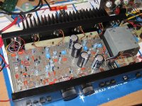
Apologies Lee,
The post, with accompanying image, from mgm31 gave my memory, a needed jolt!
The A28 (heatsink in the back) does have a speaker relay.
I don't know how I could have forgotten that since there is a recurrent problem with this relay, or not exactly the relay...
If you look closely at the image, you see two twisted wires (red and brown) beside the power transformer that are going to the main pcb. Right between where the wires are soldered, there is a small electrolytic capacitor. If you look closely, you will see that this capacitor is not the same color as the other ones, or should I say, not the same color anymore!! Too much heat as that effect on capacitors external jackets. They usually get a darker "tan" and sometimes "grow" short pants! This particular one has waaay too much on its plate. It is used in the circuit that operates the speaker relay and when it is not working properly, this is the first place where you should look. Always replace it with a capacitor of the highest voltage rating possible, as space permits. 105º C is mandatory!
The specifications for the BC639/640 and BD139/140, as destroyer X writes, are indeed very similar. You could easily replace the two drivers and bias transistors of each channel with them. It is made even easier by the fact that they have the same pinout.
I usually never do that kind of switch as I have a lot of respect for the choice of parts the designers made to build their products. Especially if the part is in the signal path!! I usually request their approval to do it and I will only do it if I can no longer find the original part or in the case of a part that is breaking too frequently. You have to understand that I do that because I feel I am professionally bound to the manufacturers the company I work for represents. I believe that even a technician working in a repair shop should follow that "code" when repairing a customer's defective unit, but that's another story...
Best regards all,
Michel
mgm31,
The A28, A28II and A28B are all coupling to their speaker through 10 mF capacitors (the 4.7 mF are used in the power supply section). The reason for that output capacitor is that the power supply used in the design is positive only. That is the reason why you do not find any negative voltages relative to ground.
Regards,
Michel
- Home
- Amplifiers
- Solid State
- Sugden P28