Hello everyone!
This is my first thread here so I hope I am in line and I start a valid conversation that hasn't been discussed too many times. I have photos of my measurements attached, even though I am not sure this is the proper way to post photos in threads.
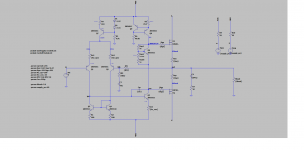
I am designing and building a Class AB output stage for a solid-state guitar amplifier. The design uses lateral MOSFETS as output devices. I used the Exicon ECX10P20 / ECX10N20 pair. I have attached a picture of the schematic below.
My problem is with the gate resistors, commonly known as gate stoppers. They are supposed to kill the speed of the MOSFET, insulating the capacitance of the gates from the VAS stage, thus avoiding HF oscillations, before they even occur.
However that is not the case in my spice simulation. All the tests in LTspice show better stability without these resistors. First of all I measured the gain margin without gate stoppers to be 8.5dB and with 221Ω gate stoppers to be 5.5dB. The phase margin without gate stoppers is at 83 degrees and with 221Ω gate stoppers it is at 81degrees (for more information on gain and phase margin refer to Bob Cordell's book "Designing Audio Power Amplifiers" - particularly chapter 4.3).
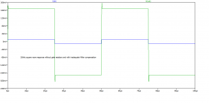
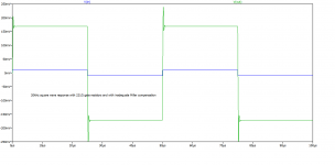
Another test that confirms my suspicions is a 20kHz square wave response measurement. To reveal the problem I made the Miller compensation capacitor Cm intentionally small, reducing it from the proper value of 220pF to 22pF, allowing oscillations to happen. The "ringing" in the edge of the square wave is hint of instability. I ran the simulation without gate stoppers and then with 221Ω gate stoppers and I have the results below. The "ringing" is much worse WITH the gate stoppers. I have also attached pictures of these measurements.
These results are very much the opposite of what I expected and it is very concerning, bearing in mind that most people are quick to point out that gate stoppers of hundreds of Ohms are ABSOLUTELY NECESSARY in MOSFET power designs. I am currently building the amplifier and I have to decide on values.
Please help. Any idea what's going on?
This is my first thread here so I hope I am in line and I start a valid conversation that hasn't been discussed too many times. I have photos of my measurements attached, even though I am not sure this is the proper way to post photos in threads.
I am designing and building a Class AB output stage for a solid-state guitar amplifier. The design uses lateral MOSFETS as output devices. I used the Exicon ECX10P20 / ECX10N20 pair. I have attached a picture of the schematic below.
My problem is with the gate resistors, commonly known as gate stoppers. They are supposed to kill the speed of the MOSFET, insulating the capacitance of the gates from the VAS stage, thus avoiding HF oscillations, before they even occur.
However that is not the case in my spice simulation. All the tests in LTspice show better stability without these resistors. First of all I measured the gain margin without gate stoppers to be 8.5dB and with 221Ω gate stoppers to be 5.5dB. The phase margin without gate stoppers is at 83 degrees and with 221Ω gate stoppers it is at 81degrees (for more information on gain and phase margin refer to Bob Cordell's book "Designing Audio Power Amplifiers" - particularly chapter 4.3).
Another test that confirms my suspicions is a 20kHz square wave response measurement. To reveal the problem I made the Miller compensation capacitor Cm intentionally small, reducing it from the proper value of 220pF to 22pF, allowing oscillations to happen. The "ringing" in the edge of the square wave is hint of instability. I ran the simulation without gate stoppers and then with 221Ω gate stoppers and I have the results below. The "ringing" is much worse WITH the gate stoppers. I have also attached pictures of these measurements.
These results are very much the opposite of what I expected and it is very concerning, bearing in mind that most people are quick to point out that gate stoppers of hundreds of Ohms are ABSOLUTELY NECESSARY in MOSFET power designs. I am currently building the amplifier and I have to decide on values.
Please help. Any idea what's going on?
Attachments
Check the gate capacitances of your fets.
Are they equal?
If not - keep reading:
============================
Let's say the 2SJ162 has a gate stopper of 100 Ohm and a gate
capacitance of 900pF, the RC time constant is just RgatexCgate=RC time constant,
so 100x900x10^-12=90nS. If we want 'balance' we need a resistance on the gate of
the 2SK1058 that gives the same time constant.
So, Rgate x 600pF = 90nS, solve for Rgate. In this case Rgate needs to be 150 Ohm.
Local instabilities of MOSFETs involve the lead inductances and coupling that are not well modeled in SPICE. The gate resistors are reducing the Q of the series resonance of the junction capacitance and the lead inductance. But they move the FET ~miller pole down and can compromise the amplifier phase margin. Keep the FET leads short and as far away from each other as possible.
Last edited:
Yes, OP is confusing local and global stability. Gate stoppers are for local stability, which is never well modeled because it depends heavily on small inductances that you probably don’t know the values of. For keeping overshoot and ringing directly across the gate-source due to these small tank circuits (which could damage the device) to a minimum. That won’t necessarily show up at the output of the amp. *Anything* that slows down overall open loop response - including gate stoppers - could degrade phase margin and result in peaking/overshoot closed loop. Completely separate issues.
The gate stopper should be set to a value that minimizes any local ringing at the gate-source, and no higher. Class D amplifiers really struggle with this - far worse of a problem and more critical to get it right.
The gate stopper should be set to a value that minimizes any local ringing at the gate-source, and no higher. Class D amplifiers really struggle with this - far worse of a problem and more critical to get it right.
Texas Instruments, back when they were making the LM4702, LME49830 wrote an application note, AN-1645 "LM4702 Driving MOSFET Output Stage" -- discusses adjusting the gate stoppers
https://www.ti.com/lit/an/snaa045a/snaa045a.pdf
https://www.ti.com/lit/an/snaa045a/snaa045a.pdf
FWIW I cut one leg of resistors to a 6-8mm stub, same with MosFet gate leg, and solder them together, so maximum "naked metal" path from resistor metal cap end to TO2** plastic body is , say, 6-8 mm total, "as short as can be" ... and never ever have problems.
On some amps (I make Bass and PA amps,not home Hi Fi ones) Power devices are away from amp board (I use aluminum back panel as heat sink and they are uniformly distributed along it) and obviously connected with up to 30 cm wires, for that use I made miniboards *just* to carry gate resistors, so they are not "floating" (wire tension and vibration during frequent transport would break them away), works like a charm.
EDIT:and agree that Simulation is a powerful and very useful tool but does not (can not) simulate many Real World problems such as wire inductance, parasitic capacitance and cross coupling.
Last edited:
You could try putting 10 nH ideal inductors in the gate, drain and source leads (about the inductance of 1 cm of wire when there is no ground plane nearby) and see what happens, especially when you apply a step straight to the output stage.
Making it a bit more accurate, you can also try modelling all wires as transmission lines, using a microstripline calculator. I normally use the one that's part of the KiCad PCBcalculator, but you can also find transmission line calculators online.
For transient simulations, it's best to use an integration method without numerical damping. The trapezium rule integration method has no numerical damping (unlike gear2 integration, which sometimes makes an unstable circuit stable), but it has the disadvantage that it messes up current waveforms, so don't panic when you see weird triangular waves riding on top of the current waveforms - it's probably just a trapezium rule artefact. The voltage waveforms are normally not affected by this.
If you should want to include electromagnetic coupling between wires, then it becomes really difficult. You need special EM extraction programs for that, that usually produce files that aren't compatible with transient analyses.
Last edited:
If you should want to include electromagnetic coupling between wires, then it becomes really difficult. You need special EM extraction programs for that, that usually produce files that aren't compatible with transient analyses.
EDIT:and agree that Simulation is a powerful and very useful tool but does not (can not) simulate many Real World problems such as wire inductance, parasitic capacitance and cross coupling.
Those programs exist, and they very very very accurately describe the electromagnetic coupling between all the various elements. The files *are* compatible with transient analysis. The problem is that you RENT them by the year, and cost some $30,000 a seat. For a year.
But they ONLY accurately describe the EM coupling. The limitations are the transistor MODELS. Getting a good high frequency model is a bitch. There are companies you can PAY to extract them. And you get what you pay for - models you get for free on the internet are worth exactly what you paid for them.
Local instabilities of MOSFETs involve the lead inductances and coupling that are not well modeled in SPICE. The gate resistors are reducing the Q of the series resonance of the junction capacitance and the lead inductance. But they move the FET ~miller pole down and can compromise the amplifier phase margin. Keep the FET leads short and as far away from each other as possible.
Yes, OP is confusing local and global stability. Gate stoppers are for local stability, which is never well modeled because it depends heavily on small inductances that you probably don’t know the values of. For keeping overshoot and ringing directly across the gate-source due to these small tank circuits (which could damage the device) to a minimum. That won’t necessarily show up at the output of the amp. *Anything* that slows down overall open loop response - including gate stoppers - could degrade phase margin and result in peaking/overshoot closed loop. Completely separate issues.
The gate stopper should be set to a value that minimizes any local ringing at the gate-source, and no higher. Class D amplifiers really struggle with this - far worse of a problem and more critical to get it right.
I had no idea that slowing down the response would move the dominant pole down. I guess I should read more, because it seems I haven't grasped the concept well enough.
Texas Instruments, back when they were making the LM4702, LME49830 wrote an application note, AN-1645 "LM4702 Driving MOSFET Output Stage" -- discusses adjusting the gate stoppers
https://www.ti.com/lit/an/snaa045a/snaa045a.pdf
pretty interesting. I will check this out
You could try putting 10 nH ideal inductors in the gate, drain and source leads (about the inductance of 1 cm of wire when there is no ground plane nearby) and see what happens, especially when you apply a step straight to the output stage. For transient simulations, the traponly integration method has the advantage that it doesn't have numerical damping (unlike gear2 integration, which sometimes makes an unstable circuit stable) and the disadvantage that it messes up current waveforms.
Making it a bit more accurate, you can also try modelling all wires as transmission lines, using a microstripline calculator. I normally use the one that's part of the KiCad PCBcalculator, but you can also find transmission line calculators online.
If you should want to include electromagnetic coupling between wires, then it becomes really difficult. You need special EM extraction programs for that, that usually produce files that aren't compatible with transient analyses.
My SPICE knowledge seems to be much more limited. I could try to put some ideal inductors on the sources and see what happens. Or I could cut straight to the testing bench and measure my prototype (with danger of destroying everything though)
Check the gate capacitances of your fets.
Are they equal?
If not - keep reading:
============================
Let's say the 2SJ162 has a gate stopper of 100 Ohm and a gate
capacitance of 900pF, the RC time constant is just RgatexCgate=RC time constant,
so 100x900x10^-12=90nS. If we want 'balance' we need a resistance on the gate of
the 2SK1058 that gives the same time constant.
So, Rgate x 600pF = 90nS, solve for Rgate. In this case Rgate needs to be 150 Ohm.
To be honest they are not equal indeed so I should use different resistor values
FWIW I cut one leg of resistors to a 6-8mm stub, same with MosFet gate leg, and solder them together, so maximum "naked metal" path from resistor metal cap end to TO2** plastic body is , say, 6-8 mm total, "as short as can be" ... and never ever have problems.
On some amps (I make Bass and PA amps,not home Hi Fi ones) Power devices are away from amp board (I use aluminum back panel as heat sink and they are uniformly distributed along it) and obviously connected with up to 30 cm wires, for that use I made miniboards *just* to carry gate resistors, so they are not "floating" (wire tension and vibration during frequent transport would break them away), works like a charm.
EDIT:and agree that Simulation is a powerful and very useful tool but does not (can not) simulate many Real World problems such as wire inductance, parasitic capacitance and cross coupling.
I will try to keep everything short. From all the above I decided I should maybe use a bit of a smaller value of resistors, something like 100Ω, because a gain margin of 5,5dB is borderline bad. If I keep everythig short and close to the leads I guess all local instabilities will be killed out.
Very often EM extraction programs produce files that are not passive outside the frequency range for which the extraction is done, so your EM model may start oscillating on its own in transient analyses. People who use those tools a lot usually know how to work around issues like that. There are also programs that can convert the s parameter file or whatever file comes out of the extraction program into a lumped circuit that's guaranteed to be passive, but always at the expense of accuracy. Besides there are different methods for port placement that often produce different results. Then again, you probably don't need extreme accuracy for simulating the effect of gate stoppers.
Convert the s-parameter model to an equivalent LCR model and the passivity problems vanish. It will likely be accurate enough for these purposes (if you are trying to simulate cavity resonances, maybe not). Passivity issues are almost ALWAYS due to mathematical shortcuts used to reduce run time. You can turn those options OFF if you have the computer power and time to wait for the answer, avoiding that issue.
That is an interesting idea too. I might go looking for small ones.
Another thing I thought was starting with a large value resistor and if it does more harm than good maybe I could connect another one in parallel. I am afraid though that this would defeat the purpose of keeping stray inductances at bay (considering my very mediocre soldering skills). Inversely I could start with smaller values and connect more resistors in series if the small value is not sufficient
Another thing I thought was starting with a large value resistor and if it does more harm than good maybe I could connect another one in parallel. I am afraid though that this would defeat the purpose of keeping stray inductances at bay (considering my very mediocre soldering skills). Inversely I could start with smaller values and connect more resistors in series if the small value is not sufficient
Available parts are 1.5mm id X 4mm od, approximately, and used on both the source and drain pins. I used some Fair-Rite type 43.
I put some on a Goldmund clone, and could hear a difference, however the 100R gate resistors may have something to do with that lack of damping. Still wasn’t expecting to notice however.
I put some on a Goldmund clone, and could hear a difference, however the 100R gate resistors may have something to do with that lack of damping. Still wasn’t expecting to notice however.
Yep, Ecler for example is using ferrite beads on FETs in their HexFet amps.

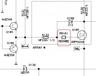
Given the high input impedance and the broad frequency response of the MOSFETs there is a high risk of self-oscillations if all gates are excited connected to the same node. Inserting a serial resistance and a ferrite bead on the gate, this possibility is minimized, because the Q of the LC network made by the inductance and gate-source capacity is reduced.
Attachments
All the tests in LTspice show better stability without these resistors.
I suggest first fixing the missing capacitor across the Vbe multiplier, so that both gates see the same AC signal and same signal impedance...
- Home
- Amplifiers
- Solid State
- Gate resistors may be the cause of instability