MPSA 42
I know the power transistors are best matched, however, does the MSPA 42 pair need to be matched?
Actually, do I really have to match ANY of them???
At 66 years, my hearing is NOT up to audiophile standards.
Thanks some much for the help.
ESP Form is a dead end, a least for me.
I know the power transistors are best matched, however, does the MSPA 42 pair need to be matched?
Actually, do I really have to match ANY of them???
At 66 years, my hearing is NOT up to audiophile standards.
Thanks some much for the help.
ESP Form is a dead end, a least for me.
First, nice build.
My amp of 10 years failed, lighting screwed up the trany, and boards screwed.
Anyway, been awhile.
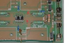
Take the Bias reading on A and B, picture, is that a CURRENT or VOLTAGE reading???
Posted on ESP Forum. Said it was CURRENT.
VR1 is a 2K 10turn. What resistance do you have on it, if its no trouble? That will get me ball park, because turning xlockwise I get ZERO and have to stop so I don't blow anything.
Got the 2 100 OHM 5 watt, lamp, and rheostat slowly up to 15+/-volts.
ISTRUCTION:
Carefully advance VR1 - with 0.33 Ohm resistors, the total is 0.66 Ohm, and for 20mA bias you will measure 13.2mV (14 - 20mV is fine) across each resistor pair. You may increase the bias current if it makes you feel better. I suggest a maximum of around 50mA per pair, or 33mV. When using ±56V or less, you can increase the current to 100mA, but this will result in a total quiescent dissipation of up to 22.4W so the heatsink will get noticeably warm.
THANKS
Hello... I measured 25mV across test points a and b. (see pic). With 0.33 ohm x 2 resistors, that is 0.66. So to figure mA take 0.66 R divided by .025 V = .038 A or 38mA
Yes. those are the measurement points. If the resistance adds up to .66 ohm (using .33 ohm resistors) at the two points, then you at the correct location for bias adjustment.
But the diagram and component values are proprietary - you should not post it...
I didn't think showing the front of the board would be bad...sorry

Thanks for removing it for me.
paul stewart, If you still have access to ESP, you can get the directions for setting bias.
One quick note...The 0.33 ohm resistors that are the easiest to clip on are the one's on the opposite side of the multi-turn pot, clip on the legs facing the pot. Hope this makes sense.
Last edited:
90 - it was not me that removed the diagram - I am a DIY stiff, not the moderator
As far as the bias clip points, one "side" of the vertical pair of the .33 ohm resistors is 0 ohms (connected), while the other side is .66 ohms. You can hold up as see the legs are on common pad. You want to be on the .66 ohm side.
Since you are already at 38ma, you have likely been biasing from the correct location. If you were measuring directly across a single .33 ohm resistor instead of the .66 ohm pair, you would not be at 38ma....you would be at twice the 38ma.
Anyway, I found the easiest bias point were the vertical resistor pair furthest away from pot and legs of these resistors closest to the center bunch of Diodes. This is A-B points
From your current 38ma - turn pot clockwise or counterclockwise and note the bias voltage, and divide this mv reading by .66 to get current in ma....turn to where you want to land across the .66 ohm resistors. The current goes through both .33 ohm resistors...
I thought I had the resistance of pot at min and was at max - and as I applied test voltage, started to smoke the emitter resistors (only with +/- 15vdc, not full voltage), luckily removed power before damage. I would finalize bias from where you are already at, as you may end of with same fate (if you minimize the pot from wrong side), but at full voltage.
From manual:
Bias Setting Information
Before applying power, check the pot with an ohm-meter! It must be at the minimum resistance setting.
You can measure this easily between the inner ends of R11 and R14 (indicated as X1 and X2 on the parts placement guide in the 'PCB Overlays' section).
Connect the amplifier directly to the main supply in the final wiring configuration. Do not connect a speaker or any other load! Connect a multimeter across one of the source resistor pairs (R12, R13 or R16, R17). Make sure that you connect to the MOSFET source end of the resistors! The points are shown as 'A' & 'B' in the layout drawing - connect to one set of 'A' and 'B' - not both.
Carefully advance VR1 - with 0.33 Ohm resistors, the total is 0.66 Ohm, and for 20mA bias you will measure 13.2mV (14 - 20mV is fine) across each resistor pair. You may increase the bias current if it makes you feel better. I suggest a maximum of around 50mA per pair, or 33mV. When using ±56V or less, you can increase the current to 100mA, but this will result in a total quiescent dissipation of up to 22.4W so the heatsink will get noticeably warm.
Last edited:
SO, It is a voltage measurement, do MATH for current.
MY PROBLEM is turning VR1 clockwise several turns gets ZERO voltage.
MY PROBLEM is turning VR1 clockwise several turns gets ZERO voltage.
Hello... I measured 25mV across test points a and b. (see pic). With 0.33 ohm x 2 resistors, that is 0.66. So to figure mA take 0.66 R divided by .025 V = .038 A or 38mA
I have been in the ESP forum. Just after several days one response and not an answer.
I did not match them.
The ESP site is still up, just in a different location than years ago (changed provider?)
I have a general question...
I have a couple 229pf high voltage safety capacitors, like Y1 500v/X1 760v. Can I use these in place of 220pf 500v caps???
Don't need them for anything else, and never will.
Thanks
IMO I don't think it would make too much difference using them in a circuit that provides surge and transient protection.
I adjusted bias to 50mA per pair. Sounds about the same as 38mA but might be the small test speakers I'm using. Still sounds great. Thanks all
I removed the RL network and set the bias back to 38mA. Sounds excellent and stays cool.
well, if I have too much trouble, I'm just going to sell all four boards and component parts.
the ESP forum is not much help, and Rod, he is just Rod.
Too small to work on. the Hx100 Ampslab looks like it will fit, fewer parts and easy acess for my failing eyes. I don't need that many watts.
thanks for the help.
the ESP forum is not much help, and Rod, he is just Rod.
Too small to work on. the Hx100 Ampslab looks like it will fit, fewer parts and easy acess for my failing eyes. I don't need that many watts.
thanks for the help.
I removed the RL network
That Zobel does have a purpose...but if you are careful (accidentally running amp without load COULD be an issue), I guess its all good.
Paul, sorry to hear of your troubles. Check the resistor values. As far as the trimmer - if its a multiturn, you may have a while to go to get the bias to show up.
I built one over ten years ago with no problems (reluctantly sold to friend who loved it), and it started on first power up...BUT my second build a few years later, I could not get to work correctly....for years it sat in a drawer... The only difference on this build, from Rod's instructions, were I ran flying leads from board to the output transistors to better fit on a heat sink / case. The ESP forum had just changed web format and was zero help (it would not even let me register)...
I finally decided to put in another (bigger) case and solder the output transistors directly onto board, as designed, and it fired right up.
There is a mistake somewhere on the PCB. A magnifying glass looking at all the solder joints to eliminate solder bridges, component verification of value and orientation... you will find it.
Its a great amp circuit, and I would not give up on it...
... The only difference on this build, from Rod's instructions, were I ran flying leads from board to the output transistors to better fit on a heat sink / case.
That should not be any issue, since manufacturers have been doing that for decades in some designs.
Even I have used that method on some mounting schemes, with no problems.
Yup, that's why it sat in the drawer for a year. Could not make sense of why it would not work. Bias was all over the place and very distorted until I soldered transistors onto board....
Rod did indicate that attempts to build the P101 without his boards would likely not work properly....and the flying leads were my issue...
Rod did indicate that attempts to build the P101 without his boards would likely not work properly....and the flying leads were my issue...
Thanks.
I am now getting .013v.
I seem to be going through some MOSFETs.
I use the basic MOSFET testing procedures. By that procedure A LOT ARE BADE. Expensive.
Are the Lateral MOFETs different???
Thanks.
ONE board out of three.
Need to order more from Ampslab.
I like there Hx100 and Hx200 kits. Come with parts.
- Home
- Amplifiers
- Solid State
- Elliott Sound Project 101 Rev C