Hi DIY friends,
I need someones electronic trouble shooting expertise in helping me diagnose an Infinity PS-10 subwoofer plate amp. I'm trying to fix this subwoofer for my younger brother.
Unit powers on (green LED lights) and changes into (Red LED lights) stand-by mode.
When an analog sound source is presented the unit plays for about 30 to 40 seconds and the sound starts to distort.
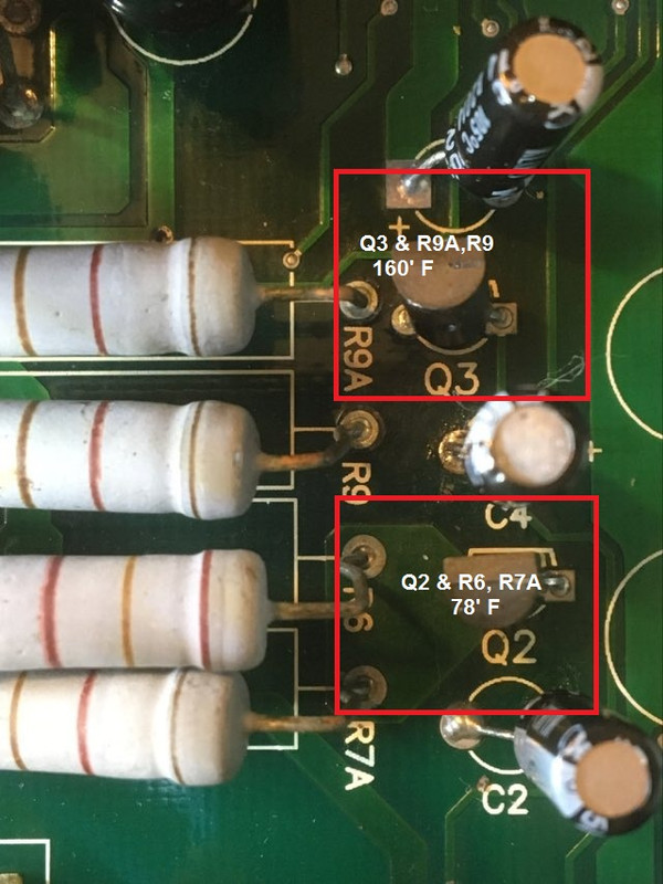
Upon first inspection I checked for any obvious signs of trouble with bad looking capacitors or fried components and nothing was apparently obvious. So I got my laser infrared temp gauge and immediately started examining individual components and when I lit up Q3 and the associated resistors R9A, R9 I observed 160 degree temps fast approaching 200 degrees Fahrenheit.
Measuring voltage from resistors R9A, R9 read 39.1 VDC
I then turned my attention to Q2 and the associated resistors R6, R7A. Temperature readings from those components was around 78.1 degrees Fahrenheit. Voltages on resistors R6, R7A were reading 51.3
I have replaced all the polarized caps in the amplifier section with Nichicon with the exception of the two large 3330uf 80v.
Capacitors Replaced:
(Two) 22uf 10% 25v
(One) 10uf 10% 25v
(One) 47uf 10% 25v
(One) 330uf 10% 16v
(One) 4.7uf 10% 50v
I have a LCR meter and pulled those two large caps and the readings were very acceptable.
I don't have a schematic and the only document I could find was the user manual. So I really don't have much to work with as far as factory specs for this unit. My assumption at this point is that Q3 is the most likely source for the problem, but I can't make heads or tails as to what the actual part# is as the printing on the transistor is micro print and not legible.
Any input from the gurus here would greatly be appreciated as my electronics skills are on the equivalent of a parts swapping monkey...
I need someones electronic trouble shooting expertise in helping me diagnose an Infinity PS-10 subwoofer plate amp. I'm trying to fix this subwoofer for my younger brother.
Unit powers on (green LED lights) and changes into (Red LED lights) stand-by mode.
When an analog sound source is presented the unit plays for about 30 to 40 seconds and the sound starts to distort.
Upon first inspection I checked for any obvious signs of trouble with bad looking capacitors or fried components and nothing was apparently obvious. So I got my laser infrared temp gauge and immediately started examining individual components and when I lit up Q3 and the associated resistors R9A, R9 I observed 160 degree temps fast approaching 200 degrees Fahrenheit.
Measuring voltage from resistors R9A, R9 read 39.1 VDC
I then turned my attention to Q2 and the associated resistors R6, R7A. Temperature readings from those components was around 78.1 degrees Fahrenheit. Voltages on resistors R6, R7A were reading 51.3
I have replaced all the polarized caps in the amplifier section with Nichicon with the exception of the two large 3330uf 80v.
Capacitors Replaced:
(Two) 22uf 10% 25v
(One) 10uf 10% 25v
(One) 47uf 10% 25v
(One) 330uf 10% 16v
(One) 4.7uf 10% 50v
I have a LCR meter and pulled those two large caps and the readings were very acceptable.
I don't have a schematic and the only document I could find was the user manual. So I really don't have much to work with as far as factory specs for this unit. My assumption at this point is that Q3 is the most likely source for the problem, but I can't make heads or tails as to what the actual part# is as the printing on the transistor is micro print and not legible.
Any input from the gurus here would greatly be appreciated as my electronics skills are on the equivalent of a parts swapping monkey...

Hi,
I see nobody has any advice to offer with regards to this amplifier issue...
I found a schematic for the Infinity PS-10 / PS-12 subwoofer amp and the MPSW56 transistor data sheet ----> LINK from Digi-key.
Maybe this will help someone in helping me out by pointing me in the right direction.
I took some voltage measurements on C5 & C10 and they are below the 15 volts the schematic states. Is this a concern?
I see from the MPSW56 transistor data sheet that this component has an operating temperature range between 55°C ~ 150°C.
My MPSW56 transistor and R9, R9a resistors are both operating at idle 224°F or 106.667°C
Does this temperature seem normal?
R9 and R9A are hot. What about R6 and R7A? If they are less hot, you know the positive rail is pulling less current, you can also see this already through your measured voltages, the negative rail is 0.57 volts below what it should be. I believe that is quite a big I*R drop, something is pulling your negative rail too hard. Maybe an open/shorted component or connection near the negative rail?
R9 and R9A are hot. What about R6 and R7A? If they are less hot, you know the positive rail is pulling less current, you can also see this already through your measured voltages, the negative rail is 0.57 volts below what it should be. I believe that is quite a big I*R drop, something is pulling your negative rail too hard. Maybe an open/shorted component or connection near the negative rail?
Thanks for following up for me drinkingcube.
I pulled R9, R9A, R6 & R7A and tested out of the board and they are testing within spec. I had corrosion on one leg of R9A from the glue on the 3300uf capacitors. I believe it was getting conductive on the top side of this 2 layer PCB. When I soldered everything back up the temps on R9, R9A, R6 & R7A all measured within 15 to 20 degrees of each other.
Also C10 now measures 15.24 volts and C5 reads 14.67 volts.
Q2 and Q3 are very hot. Temps read about 220' F
I didn't replace the two big 3300uf capacitors. Is it possible that those two caps are having an effect on the 15v rails and they could be the shorted components?