Hello Everyone...
i'm having issue with finding 2SC5198 and A1941 so i replaced 2SC5198 with 2SC5200 and A1941 with A1943 and they are running by
i didn't change these C2073 And A940
also there is A1013 transistor i didn't change that either i don't what it does but both side a1013 Getting extremely hot after few seconds,
on the left side there is Hum sound coming after 3-4 seconds when i check the output it shows Minus 9.4 volt from the speaker out before that voltage around 0.03v
sound has no issue in right side but A1013 Heating like a hell
what could be the problem?
There is no diagram
Yes found some dead C1815 replaced everything and still the same issue,
tried measure 2A104J capacitor one by one reading are also close to 104nf
but some capacitor shows around 95, so i'm going to replace all this capacitors
it takes 1 to 4 seconds to make that hum sound
could it be ceramic capacitor?
tried measure 2A104J capacitor one by one reading are also close to 104nf
but some capacitor shows around 95, so i'm going to replace all this capacitors
it takes 1 to 4 seconds to make that hum sound
could it be ceramic capacitor?
What is the make and model? Someone may have a diagram.
I would doubt any caps are the cause of the problem. Hum after a few seconds sounds more like the current is increasing to very high levels in the output stage.
Have you tried turning the bias setting down?
You should also use a bulb tester. Without circuit details it is all guesswork though.
I would doubt any caps are the cause of the problem. Hum after a few seconds sounds more like the current is increasing to very high levels in the output stage.
Have you tried turning the bias setting down?
You should also use a bulb tester. Without circuit details it is all guesswork though.
Code:https://www.youtube.com/watch?v=GKcSDZnedXk
it's not branded
This is the Exact model
no where to adjust bias setting
Thanks for suggesting i'm using a bulb tester too but speaker protection wont
power on when using Bulb
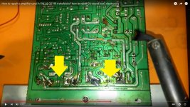
Well, one thing is for sure, that video shows how not to repair an amplifier. Inadequate soldering iron, the lifted pads, bodged wires all over the place etc.
Treat the PCB like you would treat a fine woman !

Edit: Btw, there are plenty of fake repair videos on Youtube. They don't show the working results or evidence that the repair was successful.
Just two VU meters lighted up and two speakers with no sound.
Last edited:
Well, one thing is for sure, that video shows how not to repair an amplifier. Inadequate soldering iron, the lifted pads, bodged wires all over the place etc.
Treat the PCB like you would treat a fine woman !
Edit: Btw, there are plenty of fake repair videos on Youtube. They don't show the working results or evidence that the repair was successful.
Just two VU meters lighted up and two speakers with no sound.
ha ha That's not me

You would have to be able to identify the bias generator and determine how to initially link it out and then when/if you fix the amp how to alter the values to get a suitable bias current.
Fixed bias means it can be sensitive to exact transistor types used.
that's bit advance to me but i will try
Thanks you for reply
The bias generator is usually a transistor that is in contact with the main heatsink. It could be any shape or type.
Yeah , the third man
- here for instance:Attachments
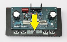
The bias generator is usually a transistor that is in contact with the main heatsink. It could be any shape or type.
Thanks it has two of S9014 transistors
Yeah , the third man
Thanks...
I Changed every ceramic capacitor on the board with brandnew ones
check each ceramic cap with multimeter they showed original value
but after replacing there is no hum or minus voltage on speaker out
but both side a1013 Getting extremely hot after few seconds,
as i see i need to find the 5198 and 1941 for sure
i think this board cannot handle 5200 and 1943
but both running with c2073 and A940
Well, one thing is for sure, that video shows how not to repair an amplifier. Inadequate soldering iron, the lifted pads, bodged wires all over the place etc.
Treat the PCB like you would treat a fine woman !
I can't bear to watch it, never mind listen to the dreadful background noise, or the shaky video
That guy is a butcher, and he's butchered that board
You would have to be able to identify the bias generator and determine how to initially link it out and then when/if you fix the amp how to alter the values to get a suitable bias current.
The bias generator is usually a transistor that is in contact with the main heatsink. It could be any shape or type.
See pic - I've arrowed them
Why would you do that ?I Changed every ceramic capacitor on the board with brandnew ones
check each ceramic cap with multimeter they showed original value
but after replacing there is no hum or minus voltage on speaker out
Ceramic caps rarely fail. were you 'upgrading' them? lol
Attachments
Last edited:
Ceramic caps are cheap and you can buy a bagful of mixed values for next to nothing. Hence you replace them when you have nothing else on hand to try. There's obviously inexperience and lack of understanding of basic electronics here so I don't hold much hope for our friend's repair.
I suggest Leema6 puts the wreck aside until later, when they have some experience with PCBs and have done some real, systematic electronics study - not just watching random "me too" DIY dummy videos. In the meantime, a much simpler kit or better still, a finished "chipamp" module of no more than say, 15W power output would be very cheap and make a much better, safer start. Before touching any PCB, he/she needs to learn to solder quickly and properly. Only use an adjustable temperature iron if you know how to set it accurately and use the right type of easy-working solder. Most people find that safe, 100% tin solder can be very difficult and slow to work with, which leads to damage of the PCB and there is a point where that damage is too much to have a reliable amplifier. Stop before making it worse.
I suggest Leema6 puts the wreck aside until later, when they have some experience with PCBs and have done some real, systematic electronics study - not just watching random "me too" DIY dummy videos. In the meantime, a much simpler kit or better still, a finished "chipamp" module of no more than say, 15W power output would be very cheap and make a much better, safer start. Before touching any PCB, he/she needs to learn to solder quickly and properly. Only use an adjustable temperature iron if you know how to set it accurately and use the right type of easy-working solder. Most people find that safe, 100% tin solder can be very difficult and slow to work with, which leads to damage of the PCB and there is a point where that damage is too much to have a reliable amplifier. Stop before making it worse.
Last edited:
i will take this as advice,
i'm still learning some stuff
Checked Voltage between transistors
C5198 BASE + EMITER I'M GETTING 0.5V
COLLECTOR + BASE 45V
COLLECTOR + EMITER 45V
A1941 BASE + EMITER I'M GETTING -0.5V
COLLECTOR + BASE - 45V
COLLECTOR + EMITER -45V
C2073 BASE + EMITER I'M GETTING 0.5V COLLECTOR TO BASE AROUND 35V
A940 BASE + EMITER I'M GETTING -0.5V COLLECTOR TO BASE AROUND 35V
A1013
BASE + EMITER I'M GETTING 6.0V
COLLECTOR TO BASE AROUND 35V
THERE ARE TWO C1815 TRANSISTOR BEFORE A1013
BASE + EMITER I'M GETTING 5.0V
COLLECTOR TO BASE AROUND 35V
AS YOU GUYS SEE WHAT COULD BE THE PROBLEM RESISTORs Value are all ok to me
A1013 getting 35v and could it be higher ampere course this to heatup
i didn't measure ampere
C1815 won't heat
WHEN I TESTING I DIDN'T TURN ON THE SPEAKER I MEAN SPEAKER PROTECTION KEEP TURNING OFF
TESTING USING LIGHT BULB
ANY IDEAS GUYS?
We can't help you without knowing the circuit/schematic diagram. There may be someone who has completed the kit and has it working but they still may not know what damage has to be repaired before it can possibly work.
In case you aren't aware, the speaker protection must turn the speakers off and remain in that state if it is going to protect the amplifier from faults which likely remain in the shorted or open output stage semis and open circuits where the PCB traces are torn and lifted from the board. Can you also be certain that you fully and correctly repaired the copper tracks and solder joints there? I doubt it, by the mangled and charred appearance of the board, but I have already suggested that you do something else before just making things worse and "worser". Ease-off and think about your progress so far - do you really think that continuing to burn the PCB is going to fix it?
There is a way to simplify problems like this by fitting only one pair of output transistors rather than the two supplied, when looking for problems. That is also an opportunity to test the power and driver transistors by comparing the test results you measure according to the best, verified test advice for power transistors that you can find. If you find differences, fit those that measure correctly and check the assembly with no load (no speaker).
There are plenty of "me too" and "idiot" videos and suggestions on the internet - hopefully you can recognise and ignore them.
We can't help you without knowing the circuit/schematic diagram. There may be someone who has completed the kit and has it working but they still may not know what damage has to be repaired before it can possibly work.
In case you aren't aware, the speaker protection must turn the speakers off and remain in that state if it is going to protect the amplifier from faults which likely remain in the shorted or open output stage semis and open circuits where the PCB traces are torn and lifted from the board. Can you also be certain that you fully and correctly repaired the copper tracks and solder joints there? I doubt it, by the mangled and charred appearance of the board, but I have already suggested that you do something else before just making things worse and "worser". Ease-off and think about your progress so far - do you really think that continuing to burn the PCB is going to fix it?
There is a way to simplify problems like this by fitting only one pair of output transistors rather than the two supplied, when looking for problems. That is also an opportunity to test the power and driver transistors by comparing the test results you measure according to the best, verified test advice for power transistors that you can find. If you find differences, fit those that measure correctly and check the assembly with no load (no speaker).
There are plenty of "me too" and "idiot" videos and suggestions on the internet - hopefully you can recognise and ignore them.
@ Leema6,
try to 'reverse engineer' the PCB. Trace the PCB copper tracks and put it on the paper. Since it's a one side copper clad board, it should be easy for you to copy the sucker. Then it will be easy for us and you to resolve the problem.
PROBLEM SOLVED

FIRST I WILL TELL THE STORY OF THIS AMPLIFIER
This is a really rat house when i get this from friend and every single wire was bitten by rat,
what i did was cleaned everything and re wire the all connection by looking at there ribbon cable pattern,
i didn't know about that LIGHT bulb safety,
when i first turn on the amplifier there is some weird sound and music played with that sound and
suddenly blow away two C5198 transistor and Two A1941,
and again i bought c5200 and tried with that safety method then i replaced few of burned c1815 A940 and C2073
then i came up with this hum issue then i replaced every 2a104J ceramic capacitor with new one,
Then again a1013 heated a lot when turning on
I Checked every single part of the transistor they were all good,
Then i found out that c5200 and a1941 collector leaking to Heat sink not fully but tiny current leaking to heatsink
Yes i used mica sheet but somehow that thermal paste had some conductivity
I cleaned heatsink and removed every excess thermal paste,
then i checked voltages and finally A1013 heating up a little but then i understand it's normal
Now Amplifier is fully working without any issue,
Thanks everyone who help me by there words,
Hope this will help someone

- Home
- Amplifiers
- Solid State
- 2SC5198 - A1941 Replacement