

If you’re going to do something that complex you might as well put an emitter resistor in the CCS, and wrap a 2N3904 around it to stabilize it. Darlingtons are going to drift even more than the single transistor he’s playing with now - possibly going out of useable range or burning up within minutes.
Yes, a JLH10W would probably be my recommendation if you are going to use several transistors.
My original thought for a constant current load would be as shown.
The emitter resistor in the PNP would need to be adjustable to set the mid point at half the supply voltage.
My original thought for a constant current load would be as shown.
The emitter resistor in the PNP would need to be adjustable to set the mid point at half the supply voltage.
Attachments
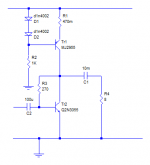
Set R1 for the desired current (half the supply divide by Z), then adjust R3 to get the mid rail voltage at the collectors.
I thought the post 21 circuit *was* the JLH at first glance, till I saw the poor connection of the 470k. In the JLH, the lower output tranny is driven from the driver/VAS emitter.
I thought the post 21 circuit *was* the JLH at first glance, till I saw the poor connection of the 470k. In the JLH, the lower output tranny is driven from the driver/VAS emitter.
Agree, both resistors need to be adjusted to match the loudspeaker load and output power needed.My thought in the previous post was to leave R3 alone as that affects the gain, but in a simple circuit like this gain and distortion are unlikely to be brilliant, so I'd agree to adjust them as needed.
(But being class A the distortion will be quite low at low volumes")
(But being class A the distortion will be quite low at low volumes
Last edited:
I experimented with a similar thing when I was a kid - in the late 60's. Mine didnt have the 3F cap and I remember the speaker cone would be sucked in a bit when on. I used a big output transistor from a car radio, with the heatsink it was originally mounted to.
I recall being bothered by the speaker suck in - enough to actually pursue a solution. I noticed the (GM) car radios had this transformer looking thing, which turned out to be an autotransformer. I used to go "hunting" for discarded car radios behind auto repair shops for parts. I even found a stereo one; two big transistors, two autotransformers.
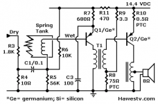
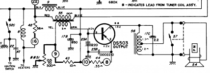
Connecting it up, it improved that aspect. I didnt know enough about electronics at the time for it to occur to me to use a resistor and capacitor couple the speaker. Attached schematics give the basic idea - there's many variations of the Delco circuit, but I wont "sign up" just to get a snap of the output stage...
Unsure if the autotransformers are unobtanium these days. Class A from the 60's! Too bad I never pursued it - never thought it'd be a thing 50 years hence! Who'd want one of these lame things when you could buy a "Lil Tiger" kit from SWTP and get 20W so easy?
I recall being bothered by the speaker suck in - enough to actually pursue a solution. I noticed the (GM) car radios had this transformer looking thing, which turned out to be an autotransformer. I used to go "hunting" for discarded car radios behind auto repair shops for parts. I even found a stereo one; two big transistors, two autotransformers.
Connecting it up, it improved that aspect. I didnt know enough about electronics at the time for it to occur to me to use a resistor and capacitor couple the speaker. Attached schematics give the basic idea - there's many variations of the Delco circuit, but I wont "sign up" just to get a snap of the output stage...
Unsure if the autotransformers are unobtanium these days. Class A from the 60's! Too bad I never pursued it - never thought it'd be a thing 50 years hence! Who'd want one of these lame things when you could buy a "Lil Tiger" kit from SWTP and get 20W so easy?
Attachments
Last edited:
My very first Transistor amplifier (mid 60´s) was just like that.
The power stage from a car radio, tapped choke loaded (a heavy DC rated autotransformer), big honkin´ Germanium transistor, probably an ASZ15 or AD149, finger blistering hot .
After replacing the second, shop attendant told me "maybe your heatsink is too small"
"Heatsink? WHAT heatsink?"
PS: we are wasting time and bandwidth with BasicHiFi1 here, he never ever takes advice and instead insists on his HUGE DC current through speaker approach.
Last edited:
When you rip the power transistor out of the old radio, you’re supposed to leave it on the original heat sink. Which was pretty big. And very expensive, if you go to order it. One of my first “big” amplifiers used the heat sinks out of two of those old Delco car radios. I wasn’t going to pay what they wanted in the catalogs for a Wakefield 423, and these were BIGGER.
I will get back to you with pictures and measurements.
In the meantime, I continue listening, and I am amazed. These are songs that I have been listening to since 1982 basically, pop songs of the day. I have listened to these on a portable cassette stereo, headphones, a full Hi Fi rack system (Technics) including a turntable, and Bluetooth speakers as well as my car stereo which is an original Pioneer system (no dashboard tweeters though).
Besides the satisfaction, actually happiness in listening to an amplifier I have put together, it sounds so clear, and even punchy. The vocals sound expressive, the mid range detailed, and these are on old speakers with muffled tweeters all located about my head.
I can only think of all the money wasted before I got here. I keep listening, and as Steve Gutenberg has indicated, that is a sign of a good system. It is addictive.
I measure 80 dB at 1 meter peak output (JBL mobile phone app).
That is called Builder´s pride/confirmation bias.I continue listening, and I am amazed. These are songs that I have been listening to since 1982 basically, pop songs of the day. I have listened to these on a portable cassette stereo, headphones, a full Hi Fi rack system (Technics) including a turntable, and Bluetooth speakers as well as my car stereo which is an original Pioneer system (no dashboard tweeters though).
it sounds so clear, and even punchy. The vocals sound expressive, the mid range detailed, and these are on old speakers with muffled tweeters
......................
I can only think of all the money wasted before I got here. I keep listening, and as Steve Gutenberg has indicated, that is a sign of a good system. It is addictive.
I measure 80 dB at 1 meter peak output (JBL mobile phone app).
Glad you are happy with your build, hope it´s just a stepstone towards a real amp.
No need for complication,you have already been suggested GOOD and simple ones.
At least keep GROSS DC out of your speakers and stop watching those 1600W Extreme Bass projects built around a transistor pulled from a CFL lamp.
At least keep GROSS DC out of your speakers and stop watching those 1600W Extreme Bass projects built around a transistor pulled from a CFL lamp.
I finally understand what you are saying: my experience listening to music took an alarming twist yesterday. I replaced the super-capacitor with something smaller, a 470 uF 50 Volt polarized. which. connected with the correct polarity allowed the thing to work. Now the super-capacitor did get a little hot, but this one really was cooking. After listening for about 10 minutes I hear a loud pop. The music kept playing, but I switched everything off. The capacitor was very very hot. It had not blown or anything but who knows...
I see what happened, originally I had connected a transformer (large 220V to 9V step down) and it had worked, however since transformers are bulky, at least that one was, and the smaller transformers not working well, I simply replaced the transformer with a capacitor. Without thinking, and without a reference circuit diagram reviewed by experts.
The videos on YouTube really show a straight through circuit, no output capacitors, no transformers, nothing. They work, but I do not know how long the speaker will last: a constant DC current through the speaker will offset the cone and also maybe burn the coils up. So no more of these videos for me. Time to listen to the experts...makes you wonder what other damage you tube is causing with its crackpot schemers.
I can see clearly now the rain is gone
I can see all obstacles in my way
Since I am in such a hurry to get music out of my speakers I will hook up an output transformer and test this thing.
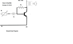
John Audio Tech has some good circuits. The large resistor looked expensive, but guess what? It comes to about 13 US cents. Well within my budget.
5W Resistors - Electronic Components Parts Shop Sri Lanka
Here is a John Audio Tech circuit, built and tested : Build this Amazingly simple class A amplifier - YouTube
Last edited:
Can I strongly urge you to take some basic learning courses in electronics?
There are some on line (I don't know any particular to recommend though but perhaps many on here can - you need a good one not a flaky You Tube, examples which of the ones I have seen are pretty dire).
In principle your circuit will work BUT there are some things you need to know, apart from the diagram being rather crude, to put it mildly. You can get circuit simulators like LT SPICE that will help to make good drawings as well as simulating the circuit.
Ordinary mains transformers are not intended to conduct DC currents any more than loudspeakers. Your 240:9V will step down an audio signal of 9V to 300mV which will give you a pretty miserable output power.
on the other hand the circuit COULD work with a properly designed transformer.
#33 You can connect the secondary winding of the transformer (9v) to the collector on the (+) power supply. Connect the speaker parallel to this winding (like a choke).#5, #26
Do not turn on 220 V winding!
I had a look at #26. The speaker is connected to a wire on one side of the transformer, so it looks like an inductor used in speaker crossovers. Won't this allow DC current into the speaker though?
Also, the measurements I said I would give for previous circuit:
Input capacitor 1 uF 50V, power off: 0.199V , power on: 0.5V. Recommended 47 uF.
Output capacitor: 3F, 2V power off: 0.966 V , power on: 4.1 V to 5.1 V about 2 minutes into operation.
VCC 11.2 V
I could manage this circuit, but I will be going down to 9V and using a single resistor, like in the John Audio Tech video.
DIY Class-A 2SK1058 MOSFET Amplifier Project
DIY Class-A 2SK1058 MOSFET Amplifier Project

- Home
- Amplifiers
- Solid State
- Simple Class A Amplifier Project