
well they are -71mv across and when you adjust them, the value changes and goes up as the lamp glows but then immediatly goes back down to -71mvThey had to be checked
So I would just look at the voltages now across one of the 0.22 ohm and see if it alters as the bulb becomes brighter.
its the -71mv bit, its pretty much a constant
something isnt right here, when you test for the idle as per the instructions i can only get +5mv on the left test point by adjustment, but if i also alter the other channel i can get it to +11mv, but then the lamp is realy bright
could something be leaking to ground?
im going to get to the bottom of this because its something simple i recon and proberbly staring me in the face.
Last edited:
71 millivolt across 0.22 ohms is over 0.3A. That is a lot. I can't really see any way for anything to flow to ground tbh.
If the transistors have been replaced for different types in the past then that might upset the bias adjustment range.
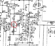
You are going to have to start at the beginning with this one. Concentrate on one channel and begin by forcing zero bias on both. You can lift this resistor to do that.
Bulb should be out and there should be no voltage across either 0.22 ohm.
If that is OK then refit the resistor and work on one channel. If the bias voltage across the resistor is to high then try a 390 ohm or 470 ohm instead of 330 ohm.
If the transistors have been replaced for different types in the past then that might upset the bias adjustment range.
You are going to have to start at the beginning with this one. Concentrate on one channel and begin by forcing zero bias on both. You can lift this resistor to do that.
Bulb should be out and there should be no voltage across either 0.22 ohm.
If that is OK then refit the resistor and work on one channel. If the bias voltage across the resistor is to high then try a 390 ohm or 470 ohm instead of 330 ohm.
Attachments
I'm getting really confused with what you are measuring here ")
There should be no interaction between channels. If you turn the bias preset on one channel up or down and the bulb goes brighter or dimmer then the control is at least doing something that it should.
So have you forced a zero bias condition on both channels? and is the bulb out or at least very dim?
Lets get it to that state first.
There should be no interaction between channels. If you turn the bias preset on one channel up or down and the bulb goes brighter or dimmer then the control is at least doing something that it should.
thats exactly what i have already done,
So have you forced a zero bias condition on both channels? and is the bulb out or at least very dim?
Lets get it to that state first.
well ive been doing realy what you said was best, be methodical
i wasnt getting the correct voltages upstream so i went back to the start, found R851 open circuit, then checked all the voltages all the way through to the output transistors and they check out with the diagram
i wasnt getting the correct voltages upstream so i went back to the start, found R851 open circuit, then checked all the voltages all the way through to the output transistors and they check out with the diagram
it is zero bias on both, this is with the pots in the positions as instructed before you attempt to make adjustment vr603 fully clockwise and vr604 fully anti clockwise.I'm getting really confused with what you are measuring here
There should be no interaction between channels. If you turn the bias preset on one channel up or down and the bulb goes brighter or dimmer then the control is at least doing something that it should.
So have you forced a zero bias condition on both channels? and is the bulb out or at least very dim?
Lets get it to that state first.
with these in those positions the lamp is very dim but as you adjust them the lamp gets brighter, but no change on the meter reading.
on the instructions it refers to TP1 and TP2 ok,
A-method-so ive been using the bottom pin common to both resistors and i get 0v and no movement.
B-method-if you use either of the top pins you can adjust it to say 8mv and what you end up with is -8mv on the other side which i guess you would expect
with both sides adjusted the lamp is still fairly well lit up.
so which pin would you use, it doesnt specify in the instructions
Attachments
I'm getting really confused with what you are measuring here
There should be no interaction between channels. If you turn the bias preset on one channel up or down and the bulb goes brighter or dimmer then the control is at least doing something that it should.
So have you forced a zero bias condition on both channels? and is the bulb out or at least very dim?
Lets get it to that state first.
so an update on my last post.
in the end i stumped reluctantly to good old youtube and watched a guy doing the adjustments on there
doing it his way, which was to connect leads across the resistor and adjust the pots that way i have both bias currents set at 8mv and the centres at 0v, but the lamp is still lit up a bit, so maybe some other faulty component in the circuit i just have to find?
the lamp should be off right?
I'm getting really confused with what you are measuring here
There should be no interaction between channels. If you turn the bias preset on one channel up or down and the bulb goes brighter or dimmer then the control is at least doing something that it should.
So have you forced a zero bias condition on both channels? and is the bulb out or at least very dim?
Lets get it to that state first.
im wondering if im actualy chasing nothing now
all the voltages seem ok, the centre is 0v on both and the idle 8mv on both
the lamop is still on a bit though, so this is realy whats bothing me at the moment, or is it not a prob?
there is a buzz on both speakers if you plug them in so ive taken them out for now
Last edited:
The lamp will glow when you have bias current flowing. So not a problem.
Just remember to make sure the adjustment is still correct when on full mains as it can change with the higher supply voltage.
The centre pin of the resistor pack will go to the speaker output and so measuring from speaker + to that centre pin would always show as 0 volt. If the manual says to do it that way then it is wrong. You have to measure across one of the resistors which you seem to be doing.
8mv will about 36 milliamps current
A buzz a loud buzz, a quiet buzz. It needs quantifying and checking. Does it change with the volume control for example.
Just remember to make sure the adjustment is still correct when on full mains as it can change with the higher supply voltage.
The centre pin of the resistor pack will go to the speaker output and so measuring from speaker + to that centre pin would always show as 0 volt. If the manual says to do it that way then it is wrong. You have to measure across one of the resistors which you seem to be doing.
8mv will about 36 milliamps current
A buzz
a loud buzz, a quiet buzz. It needs quantifying and checking. Does it change with the volume control for example.its a bit like when you get electrical interference, doesnt change with volume adjustment
a bit like you used to get in car years ago when you needed to fit a supressor on the dynamo or a bit like a noise from a transformer
i also get a noise if i touch the pre amp/power amp jumpers-comes through on the speaker-grounding?
i keep finding odd things
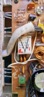
R676 should be a 2w 680ohm, but what was in there, if the colours are right is a 390meg ohm(orange,white violet) yet it reads 490 ohm on the meter
i replaced the 680ohm with one out of another amp
a bit like you used to get in car years ago when you needed to fit a supressor on the dynamo or a bit like a noise from a transformer
i also get a noise if i touch the pre amp/power amp jumpers-comes through on the speaker-grounding?
i keep finding odd things
R676 should be a 2w 680ohm, but what was in there, if the colours are right is a 390meg ohm(orange,white violet) yet it reads 490 ohm on the meter
i replaced the 680ohm with one out of another amp
Last edited:
if the colours are right is a 390meg ohm
That's very resistory
It may as well not be there
well i think im almost there(as andy williams used to say )
i have sound coming out, well kind off, the pre amp boards at the back must have poor connections because i get sound out of the right speaker, and when i twist the casing the buzzing sound changes pitch and goes quiter
) i have sound coming out, well kind off, the pre amp boards at the back must have poor connections because i get sound out of the right speaker, and when i twist the casing the buzzing sound changes pitch and goes quiter
R676 could have been a 390 ohm as brown and violet can look a bit similar. It feeds the relay so the basic check is to look at the voltage actually across the relay coil and see how it matches up to the marked value on the relay.
390meg would be about the same as 100 yards of string
If physical movement effects the buzz then there is a bad connection/s somewhere.
390meg would be about the same as 100 yards of string
If physical movement effects the buzz then there is a bad connection/s somewhere.
bad connections lol i should say
so:
idle is all good plugged in without the lamp-steady at 8mv
centre is all good at 0v +/- 2mv
sounds ok, the pre amp had a plug in board 10 loose connections i found on that! so i reflowed all the joints
all good now, boy that was a marathon, but i still enjoyed doing it, even if it was a bit frustrating at times
If the resistor is in series with a relay coil, sitting there running hot day in and day out, it could turn brown into violet easily. Discoloration is a sign of long term (over)heating. And if it does read 490 ohms that pretty much confirms that it’s running too hot - values tend to go *up*. Probably using 1/2 watt carbon film when they really needed 2 watt MOX or WW for long term stability.
sounds ok, the pre amp had a plug in board 10 loose connections i found on that! so i reflowed all the joints
all good now, boy that was a marathon, but i still enjoyed doing it, even if it was a bit frustrating at times
Well it is a NAD
You should be getting to be the sites resident expert on these now
Get something else to play with next time
- Home
- Amplifiers
- Solid State
- NAD 3150