Well, to Osvaldo's point, I want to test/confirm that the bass pot (either the caps or the mechanical pot itself) is the cause of the issue. I did try disconnecting the two wires going from the tone controls to C3 and R15 for just one channel. This caused some other artifacts to appear on the waveform, but it did not cause the spikes shown in the video I posted to disappear. Does this rule out the pot? Or is there a better way to test whether it's the culprit?
I disconnected the preamp board from the amp, and no change.
Looking at the power supplies with my scope AC coupled 20mV/div .2ms/div, I'm seeing the following where the 25V B1+ enters the amp/tone board:
B1+ Amp Board - YouTube
I've already replaced C410A, but nothing else in this particular part of the power supply:
Looking at the power supplies with my scope AC coupled 20mV/div .2ms/div, I'm seeing the following where the 25V B1+ enters the amp/tone board:
B1+ Amp Board - YouTube
I've already replaced C410A, but nothing else in this particular part of the power supply:
Attachments

This important. So if disconnecting the pre the problem continues, at first instance pre is discarded. So let me know where you diconnected the amp and let me see if there is another link to break. Also try a new C3 in the 401 board (50uF), and if possible, put there 220uF or more with proper vw.
Last edited:
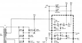
I disconnected the preamp from the amp at C1. (Circled in orange.)
For the power supply cap you suggested replacing, are you sure you want me to swap out C3 and not C2? It's the B1+ 25V, not the B5+ 25V that I saw that AC on.
For the power supply cap you suggested replacing, are you sure you want me to swap out C3 and not C2? It's the B1+ 25V, not the B5+ 25V that I saw that AC on.
Attachments
I'm not viewing the entire schematic. The phone's screen is small. I mean the cap filter that gives supply for the preamp section. Also try to cut at C3 on the amp to completelly disconnect amp from pre and leave power stage alone. In case of doubt replace both C2 and C3 on the 401 board in parallel to both zeners.
Also it's confusing for me that there are repeated identificators for parts nubers/names and the fact that positive rail is under the scrematic and not above as usual.
Also it's confusing for me that there are repeated identificators for parts nubers/names and the fact that positive rail is under the scrematic and not above as usual.
Last edited:
Note www.www.justradios.com has more axial lead electrolytic cap values than www.newark.com or DigiKey Electronics - Electronic Components Distributor. The vishay axial lead caps from the latter may lost longer however. If you have multigang can caps, they are available from Antique Electronic Supply but I've found in organs it is a lot quicker to screw a 5 eyelet solder terminal strip across the hole and install 3 or 4 radial lead electrolytic caps. Radial electrolytic caps from panasonic, nichicon, or rubicon can be bought in service life grades up to 12000 hours, which should solve the problem I've had of replacing the same electrolytic cap over & over, up to 4 times. Antique Electronic Supply has more panel mount potentiometers than newark or digikey or mouser.
The solder terminal strips with the mount on the end are most useful for replacing can caps. https://www.tubesandmore.com/products/terminal-strip-5-lug-0-common-horizontal Use elastic stop nuts on #6 screws so they don't come loose.
Try to load your film cap in the same box. The cap is <$1, the rate to ship a box is $8 up. Mouser gets me $14 shipping every time, then ships air freight for some reason.
Last edited:
Wait a moment, dear. Let the guy find the part(s) causing his headache and after it we see how he want/can to put new parts.
His amp is motorboating. In my experience, never a tone control stage had caused such a symptom. Nor a small film cap. Usually it is as a consequence of improper bypassed power supply, be by bad design, be by degraded caps.
Salu2 para to2.
His amp is motorboating. In my experience, never a tone control stage had caused such a symptom. Nor a small film cap. Usually it is as a consequence of improper bypassed power supply, be by bad design, be by degraded caps.
Salu2 para to2.
I was going to give an old preamp (cap coupled) to one of my friends. I hooked it up to one of my systems and everything worked. Then I hooked it up to my shop system and the power amp wouldn't come out of protect. A little sleuthing showed 0.5 volts DC between audio ground and the electrical service ground. I haven't figured out why (probably the safety circuit) but obviously something's up.
The difference between the power amps is that the shop power amp used a grounded plug.
The difference between the power amps is that the shop power amp used a grounded plug.
Sometimes audio ground is isolated from power gnd by a conductive network like a high valued R like 100K and a cap of,say, 0.1uF. Other uses two diodes in antiparallel. Perhaps some leak current is the cause of such voltage drop. One example may be Y caps in the ungrounded kit. Also contact potentials between joining of different metals can give up to 1V across them.
Last edited:
He has a scope reading of jumps up near C105 or C106. Near those and the bass pot. Plastic film caps are usually reliable, but not always in 1965. SCR cap of France became notorious on this forum. Some vendors had trouble spraying the metal paste properly to not leak across the ends. I got some leaky film caps, 90 kohms @ 2 volts, from a surplus house. The picture OP showed is not one of the usually reliable brand film caps. It is not unheard of in 1965 for this to be a paper dialectric cap, which have definitely deteriorated in some of my 1964 organs and 1961 dynakit products.His amp is motorboating. In my experience, never a tone control stage had caused such a symptom. Nor a small film cap. Usually it is as a consequence of improper bypassed power supply, be by bad design, be by degraded caps.
.
The electrolytic suggestions are to ease implementation of your suggestion about the power supply cap, c3 on power supply board?
He can do further scope probing while a box grinds its way through the postal system. 8 days on some boxes, 32 days on another? Yes, USPS can move 2 day rate boxes in 2 days, sometimes. FedEx took 8 days on a surface rate box from AZ in August. Too many workers in a Colorado hub out quaranteened, and fires in Oregon & California closing hubs. Tubesandmore.com is in AZ.
I'd buy every electrolytic cap in the amp in the same box. they are going to fail one by one if he uses this more than an hour or two. I used a 1961 amp ~20000 hours and a 1970 amp ~14000.
Last edited:
Thanks Oswaldo and indianajo. I appreciate both of you sticking with me on this as I try to sort out what the heck's going on. This combined tone/amp board design makes me appreciate receivers and integrateds that have main in/preamp out jumpers even more. 
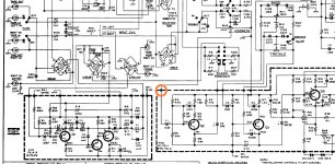
Oswaldo: I've attached the full schematic of the preamp, tone, and amplifier sections, as well as of the power supply. Hopefully, the resolution is good enough.
I tried disconnecting the amp board from the tone controls at C3 on the amp board. No change; the issue persisted. I still need to replace those caps (C2 and C3) on the power supply board. Stay tuned.
indianajo: Thanks for the tip about axial caps at justradios.com I do often use the Vishays, but they add up $$. As for the cans, I've gone both ways. If I'm fixing someone else's gear and they want to spend the money, I'll get them from Hayseed Hamfest. But if it's just for me, I'll either restuff the originals or bypass them using terminals strips and radial caps like you suggested.
Attachments
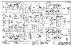
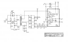
Oswaldo: I've attached the full schematic of the preamp, tone, and amplifier sections, as well as of the power supply. Hopefully, the resolution is good enough.
Resolution is OK for me. I'm viewing it in a small screen.
Please, acclare to me where are you seen the problem. At loudspeaker output or somewhere inside the circuit.I tried disconnecting the amp board from the tone controls at C3 on the amp board. No change; the issue persisted. I still need to replace those caps (C2 and C3) on the power supply board. Stay tuned.
The audible difference between 1Cent cap and a 100U$S is negligible. So don't worry about it. It is only a question of Marketing. Pure marketing as Messi is.
Do you have a 50W light bulb of the filament type? If is the case, wire it at the lousdpeaker's terminals almost in one channel. And tell me what do you see in it.
Last edited:
Some equipment won't get fixed without a fight. Sigh.
The amp boards are sandwiched together pretty close, and a slip of my scope probe took out Q4, Q5, and one output in the right channel. I replaced Q4 and Q5, and installed a different set of outputs. Now that channel isn't biasing up--turning the bias trimmer has no effect. My DC balance voltages look fine, and I've tested most of the components in the area, with the exception of the caps. The anomaly I'm seeing is at Q4 in the right channel. It tests fine out of circuit.
Q4 (Left)
E: 35.7
B: 35.3
C: 1.11
Q4 (Right)
E: 35.4
B: 34.7
C: 0.62
Something pulling down the voltage at the collector?
Last edited:
Sometimes audio ground is isolated from power gnd by a conductive network like a high valued R like 100K and a cap of,say, 0.1uF. Other uses two diodes in antiparallel. Perhaps some leak current is the cause of such voltage drop. One example may be Y caps in the ungrounded kit. Also contact potentials between joining of different metals can give up to 1V across them.
LOW valued resistor like 10 Ohm 2W.
Haven't read the whole thread but C404 should be at least 4700 µF if the device is meant to drive real loudspeakers. Are all the rectifier diodes checked? I have had my share with very old diodes causing strange things.
Last edited:
With no signal, I'd pull one leg of C114 to see if it is leaking. Part of AC comp I'd guess, so at DC not important. Test with circuit, not the 2v stress of a meter ohms scale.I replaced Q4 and Q5, and installed a different set of outputs. Now that channel isn't biasing up--turning the bias trimmer has no effect. My DC balance voltages look fine, and I've tested most of the components in the area, with the exception of the caps. The anomaly I'm seeing is at Q4 in the right channel. It tests fine out of circuit.
"Tests okay" after a high voltage transient is a gloss. Things like D1 can be fine at 2 v the meter tests at, but leak like a sieve at 35 v. I test stressed parts with 12 v through a 47k ohm resistor, then the microamp scale of the DVM. Couple of microamps, the parts is okay, 255 microamps the parts is breaking down. Works on C to E of transistors too with the base disconnected.
Warning, modern transistors for 1965 parts, especially ones out on an external heat sink with long leads, can oscillate. Much higher Ft after epitaxial was invented. 10 ohm 1 W resistor as base drive instead of the wire is the usual correction.
Answer to Jean-Paul's prompt, 4700 uf caps in 1965 were very expensive. This amp is designed to run with 1000 uf for C404. More would require some part to not stress the transformer at turnon. Also more C404 could add to bass thump at turn on. Carefully designed 1965 amps didn't thump at turn-on, although they didn't have the half dozen silence at turn on parts later circuits had. My ST120 dynakit doesn't thump,1966 design, & uses 3300 uf rail cap for two channels @ 60 w/ch. I've gotten 70/ch w out of it for 5 seconds with MJ15003 outputs instead of original RCA selected 2n3055. 40111 was it? burned transistors had a dynaco PN on them. Still a single 3300 uf rail cap.
Last edited:
It was then more or less like that. Large values were physically too large for equipment and they were indeed too expensive. If designers would have had 2200 or 4700 µF caps in todays sizes they would have used them Since the amplifier is AC coupled the turn on thump will not damage much I guess.
What about the spikes? Can they be seen on the PSU voltages?
Since the amplifier is AC coupled the turn on thump will not damage much I guess. What about the spikes? Can they be seen on the PSU voltages?
With no signal, I'd pull one leg of C114 to see if it is leaking. Part of AC comp I'd guess, so at DC not important. Test with circuit, not the 2v stress of a meter ohms scale.
"Tests okay" after a high voltage transient is a gloss. Things like D1 can be fine at 2 v the meter tests at, but leak like a sieve at 35 v. I test stressed parts with 12 v through a 47k ohm resistor, then the microamp scale of the DVM. Couple of microamps, the parts is okay, 255 microamps the parts is breaking down. Works on C to E of transistors too with the base disconnected.
Warning, modern transistors for 1965 parts, especially ones out on an external heat sink with long leads, can oscillate. Much higher Ft after epitaxial was invented. 10 ohm 1 W resistor as base drive instead of the wire is the usual correction.
Answer to Jean-Paul's prompt, 4700 uf caps in 1965 were very expensive. This amp is designed to run with 1000 uf for C404. More would require some part to not stress the transformer at turnon. Also more C404 could add to bass thump at turn on. Carefully designed 1965 amps didn't thump at turn-on, although they didn't have the half dozen silence at turn on parts later circuits had. My ST120 dynakit doesn't thump,1966 design, & uses 3300 uf rail cap for two channels @ 60 w/ch. I've gotten 70/ch w out of it for 5 seconds with MJ15003 outputs instead of original RCA selected 2n3055. 40111 was it? burned transistors had a dynaco PN on them. Still a single 3300 uf rail cap.
I'll try lifting C114. And to your point about things testing ok and failing in circuit, I was wondering if D1 really is ok. Any suggestions for what I can use there? Even accessing it for testing is a bit of a pain, and I might just replace it.
Re the outputs I swapped in, they're matched RCA 2N3055s I had on hand.
- Home
- Amplifiers
- Solid State
- DC Offset with Cap Coupled Amp