I'd like to build a power booster for a low watt tube guitar amplifier that I recently built. The guitar amp produces about .5 watt sine and maybe 1 watt max. Great for practicing at home.
I saw a design for a power booster using tubes but only achieves a power gain of about 6. I'd like something more in the range of 60 - 100 to get me to 30 - 60 watts for playing out. Using some less common tubes it could be achievable but I like to stick to stuff that readily available.
Ideally, the booster doesn't change the dynamic interaction between the speaker and the tube amp's output section.
Mosfets are maybe a better choice for the application? This is an area I where I'm seriously lacking experience.
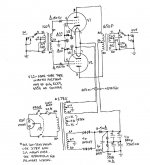
Would a common grid setup like this have a chance of working?
I saw a design for a power booster using tubes but only achieves a power gain of about 6. I'd like something more in the range of 60 - 100 to get me to 30 - 60 watts for playing out. Using some less common tubes it could be achievable but I like to stick to stuff that readily available.
Ideally, the booster doesn't change the dynamic interaction between the speaker and the tube amp's output section.
Mosfets are maybe a better choice for the application? This is an area I where I'm seriously lacking experience.
Would a common grid setup like this have a chance of working?
Attachments
You have no bias voltage in the first circuit, I presume its just a rough indication of topology. Unless you use lateral FETs you'll need to consider thermal stability of the bias point.
I presume you are chosing common-gate as you have power available at the booster input and don't want to throw that away. Its a common approach for RF amplifiers for the same reason.
However if you are wanting 18 to 20dB of gain the input power is not so much an issue and a standard amplifier setup would be an option - terminate the guitar amplifier into 8 ohm power resistor (or whatever the speaker impedance is), and just put that through another power amp (possibly attenuating a bit, as 1W at 8ohms is 2.8Vrms which is high for line-level.
Well you won't achieve that, a buffer / amplifier provides a lot of insolation between source and load by its nature.Ideally, the booster doesn't change the dynamic interaction between the speaker and the tube amp's output section.
I presume you are chosing common-gate as you have power available at the booster input and don't want to throw that away. Its a common approach for RF amplifiers for the same reason.
However if you are wanting 18 to 20dB of gain the input power is not so much an issue and a standard amplifier setup would be an option - terminate the guitar amplifier into 8 ohm power resistor (or whatever the speaker impedance is), and just put that through another power amp (possibly attenuating a bit, as 1W at 8ohms is 2.8Vrms which is high for line-level.
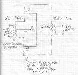
Thanks Mark, the first circuit is just a very crude topology. The Second circuit is the one I want to boost.
The idea originated from the attached circuit which the creator claims "maintains the interaction between the input amplifiers output section and the speaker" It was designed to boost the output of a 10watt amp to 60watts.
It operates in class B I believe.
The idea originated from the attached circuit which the creator claims "maintains the interaction between the input amplifiers output section and the speaker" It was designed to boost the output of a 10watt amp to 60watts.
It operates in class B I believe.