I am new to the forum, I don't have much electronic expertise but have been an avid hifi fan most of my life.
I bought my PL 700B twenty years ago and it had been in storage since 1980. It had been checked over and had a clean bill of health and sounded brilliant.
After running it for a few months it sent some feedback down one of the channels and burned out a speaker.
I went to the best technician I could find and after 3 tries and many components replaced it still had the problem. It was still frying speakers, most of the time it worked fine but if the feedback hit it was too late for the speaker. He said he didn't know what the problem was and his only suggestion was to replace all the components inside. I gave up parked it up, I hated frying my beautiful speakers.
Being in Sydney, Australia I didn't have a lot of options as far as getting it repaired. They are rare out here so finding someone with the necessary expertise is difficult.
I would like to get it repaired properly but want to be armed with a bit of info before I give it to someone.
I was hoping that someone had encountered this problem before and could point me in the right direction.
Thanks in advance
Peter
The usual cause is semiconductor failure caused by instibility.
Unfortunately I cannot comment more without working on it.
Here is the schematic; PHASE LINEAR 700B Service Manual download, schematics, eeprom, repair info for electronics experts
Unfortunately I cannot comment more without working on it.
Here is the schematic; PHASE LINEAR 700B Service Manual download, schematics, eeprom, repair info for electronics experts
Is this “feedback” an ultrasonic oscillation, or is the noise actually audible? Both are equally possible. I had a PL400 develop an intermittent connection to the VAS transistor (RCA 40412 on the little pcb mount heat sink) that produced short spikes of DC to the speaker (at the full 75 volts) that would happen at random. Every time if had a glitch, it produced a very loud audible chirp as the negative feedback tried to correct the anomaly. Upon inspection, the whole board was full of solder joints that needed reflowing. There are a lot of parts that get hot on the driver board. It’s worse on the 700 because of the higher supply voltage.
You could try putting an aftermarket DC detect & disconnect circuit between the amp & speaker. Packaging such is a problem. You might be able to squeeze two in the amp, but you might have to add a separate chassis with its own power supply.
There are a number of threads about DC detection circuits. One on SS forum recommends a $5 Ebay board. Most such boards lack the quality of relay necessary to disconnect 1000 ADC. Cheap relays weld the contacts shut under heavy DC loads.
Certainly the driver transistors need their own heat sinks driving 5 output transistor pairs. 40412 is a rare TO5 part with 50 mhz Ft, that is most often replaced by inferior 3 mhz parts (mostly no Ft rating at all) by such sources as NTE or Central Semi. EBC transistors are rare these days in 20 to 100 W rating; most replacements are BCE, which doesn't fit. I damaged my PCB on a board with TO5 drivers and had to replace it with a more modern design.
Really if you need that much wattage a PA amp with built in DC detect disconnect would be a more sensible solution. Such class AB amps in the 300-700 w/ch variety are cheap these days, as bands don't want to carry a 80 lb chassis to set up & tear down every night. Peavey CS800s, cs800x(square air tunnel in front), and crown XLS402 come to mind. Even early CS800 are useful & can be reliable, if one changes the 741 input op amp for something with less hiss like a TL071 or OPA604.
+--100 v rails is obsolete and not necessary for amps with output <2000 W. The high voltage was necessary before 1980 because power transistors had poor gains. A problem solved by Motorola & others after this amp hit the market. My PV-1.3k with 650 w/ch 4 ohms has +-85 v rails.
Last edited:
The usual cause is semiconductor failure caused by instibility.
Unfortunately I cannot comment more without working on it.
Here is the schematic; PHASE LINEAR 700B Service Manual download, schematics, eeprom, repair info for electronics experts
Thanks for the link. Is that the whole manual in one page?
The schematic would be really helpful if I can find a tech to fix the amp.
Is this “feedback” an ultrasonic oscillation, or is the noise actually audible? Both are equally possible.
The feedback was a loud buzz and pretty sure was continuous until I could shut the power off. By then the speaker was fried, left channel only.
You could try putting an aftermarket DC detect & disconnect circuit between the amp & speaker.
Really if you need that much wattage a PA amp with built in DC detect disconnect would be a more sensible solution.
DC detect & disconnect circuit is something I will look into. 20 years ago my tech said that there wasn't a protection circuit big enough the handle the power of the 700B.
I did replace the PL with a big PA amp but the sound quality wasn't there.
Since replaced with an Adcom GFA-585 which I really like. I haven't done a back to back with the PL to know which I would prefer.
I have had my Polk 12A speakers since 1985 and still love them but they are very power hungry. I ran them with a Carver Cube for many years and fried the tweeters numerous times. I contacted Polk and the tech told me I needed an amp with much more dynamic headroom than the Carver, hence the 700B.
Having it sit idle in the cupboard for 20 years is like having a great old car in the garage that doesn't run, I would like to see it back in action.
Raise the issue on the phase linear site
Phoenix Audio Community Forums
Thanks for that, I will try this forum, I would never have made the link between Phoenix and PL.
A “loud buzz” could be a result of “DC to the speaker”. The main filter caps are very small for an amp that size, and if it heads for the rail due to some fault there will be A LOT of AC ripple mixed in with the DC, resulting in a loud hum/buzz at 120 Hz plus lots of harmonics. I would be looking for one of those intermittent connections. It’s probably worse than the one I had in mine, if it latches up and stays that way. It is also quite possible the main filter caps are dried out, and that would make even more AC ripple than there is supposed to be. You wouldn’t actually hear the buzz if the amp were behaving normally if the caps are dried out, but it would put out less power than it should.
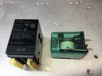
The cute little pcb mounted relays in typical HT receivers aren’t big enough to open properly in the event of a DC fault in an amp that size, but something the size of one of these is. They would arc over and weld if you tried to break a 500 amp fault into a short circuit, but limited by a 3.5 ohm voice coil it will get into the 40 amp range where it will open.
Attachments
High amount of DC on the output would kill a speaker.
Even though there was a shotgun repair attempt of replacing a lot
of components.
The problem seems intermittent
and can be easy or difficult to diagnose.
As mentioned likely a connection issue.
Sometimes a bad connector or solder joint
is visually obvious. Otherwise intermittent
connections are difficult to find sometimes.
almost a ridiculous process of jiggling and wiggling
connectors. Or applying pressure to the boards
to find where the bad connections are.
loosing emitter on the second gain stage or vas
could latch to full rail.
Or if input ground is lost.
DC protection would help save the speakers.
High power DC protection with larger PA style amplifiers
usually start using crowbars. Which are typically very
destructive for the amplifier. But do save very expensive
speakers.
Curious if a simple solid state/ mosfet relay could help
Last edited:
These things are sort of famous for doing this. Some people even called them "flame linears" for this reason. Here are a few reasons why they are reputed to blow up.
1) There is NO protection circuitry in these things. No VI limiting, no short circuit protection, no DC protection, none of that.
2) They had woefully inadequate heatsinking for the size of the amplifier. This really wasn't a huge problem for their intended application -HiFi systems- but proved to be a BIG issue when people started using them as PA amps for rock shows.
3) There is NO peak limiting in these things at all to protect the amplifiers from being overdriven. This blows up both speaker drivers and amplifiers.
4) They are a really big amplifier by today's standards, and by 1970s standards, they were some of the biggest power amplifiers in the world. That meant that when they do go thermonuclear, it's exciting and usually takes other equipment (like speaker drivers) with it and sometimes burns up the PCBs in the amplifier.
Surprisingly, they can be made to be very reliable. Here are a few suggestions:
1) Peak limiters! Lots of ways to do it, but this stops you from ever being able to overdrive the amplifier.
2) Make sure ALL of the transistors are the same (and there are better devices on the market today than the originals that were used in the 1970s), and make sure that they are properly greased and torqued to the proper specification. Check a transistor datasheet (all the TO-3 transistors should be about the same in this regard) for this spec.
3) Make sure any electrolytic bypass caps have been replaced and that the amplifier is electrically in good working order. You CANNOT let this amplifier oscillate. I've seen one or two that became borderline unstable with age as the electrolytic caps tried out. IIRC, there are no ceramic / poly film bypass caps in it, so adding those might be a good idea.
4) If you're going to push it at all or drive low-impedance loads, putting a fan on them is a very good idea.
If they're looked after, they're really a pretty good amplifier that is has some cool historical value. Also, the rail voltages in these are pretty high, so be careful. Slipping with a meter probe is bad news.
DC protection would help save the speakers.
High power DC protection with larger PA style amplifiers
usually start using crowbars. Which are typically very
destructive for the amplifier. But do save very expensive
speakers.
Curious if a simple solid state/ mosfet relay could help
I don't like using crowbars. There are more elegant ways of doing it. You can sometimes get away with a beefy mechanical relay if it shorts the speaker load to ground when it opens. The relay will be destroyed, but it very often will succeed in saving the speaker. Quenching magnets on the relay can also help.
You can also use a SSR (obviously one based around SCRs or Triacs isn't going to work here). Others have been quite successful with devices like this.
Phase Linear
Posted:
These things are sort of famous for doing this. Some people even called them "flame linears" for this reason. Here are a few reasons why they are reputed to blow up.
1) There is NO protection circuitry in these things. No VI limiting, no short circuit protection, no DC protection, none of that.
2) They had woefully inadequate heatsinking for the size of the amplifier. This really wasn't a huge problem for their intended application -HiFi systems- but proved to be a BIG issue when people started using them as PA amps for rock shows.
3) There is NO peak limiting in these things at all to protect the amplifiers from being overdriven. This blows up both speaker drivers and amplifiers.
4) They are a really big amplifier by today's standards, and by 1970s standards, they were some of the biggest power amplifiers in the world. That meant that when they do go thermonuclear, it's exciting and usually takes other equipment (like speaker drivers) with it and sometimes burns up the PCBs in the amplifier.
Surprisingly, they can be made to be very reliable. Here are a few suggestions:
1) Peak limiters! Lots of ways to do it, but this stops you from ever being able to overdrive the amplifier.
2) Make sure ALL of the transistors are the same (and there are better devices on the market today than the originals that were used in the 1970s), and make sure that they are properly greased and torqued to the proper specification. Check a transistor datasheet (all the TO-3 transistors should be about the same in this regard) for this spec.
3) Make sure any electrolytic bypass caps have been replaced and that the amplifier is electrically in good working order. You CANNOT let this amplifier oscillate. I've seen one or two that became borderline unstable with age as the electrolytic caps tried out. IIRC, there are no ceramic / poly film bypass caps in it, so adding those might be a good idea.
4) If you're going to push it at all or drive low-impedance loads, putting a fan on them is a very good idea.
If they're looked after, they're really a pretty good amplifier that is has some cool historical value. Also, the rail voltages in these are pretty high, so be careful. Slipping with a meter probe is bad news.
I am not saying that PL amps were good. They are really nasty amplifiers especially with those PL909 output devices.
Please get your facts straight H713.
Every PL amplifier has volt - amp limiting = short circuit protection. They are single slope types but work OK.
.
The circuit is about the crudest one could think of. Crossover distortion changes as the rails sag due to the fact that the VAS stage has no constant current device.
The bootstrap resistors + capacitor is simply dumb design.
Older PLs had no constant current sources for the diff amps with no local degeneration and no means to slow down the drive to the output tripletts.
When series II arrived with that dumb A$$ LF351 IC as the front end things went from bad to worse.
The bottom line is that modifying these amps is like putting lipstick on a pig....it is still a pig.
One company in the US offers kits to kind of add the lipstick, 1% metal films, yes better 15v regs and so on but they are still pigs.
Sure no DC protection was ever installed
Suggest contact watts abundant re rotection circuit, they appear to make one for both the 400 and 700, even if it "only" handles 350W it would serve a purpose.
OUTPUT RELAY
rotection circuit, they appear to make one for both the 400 and 700, even if it "only" handles 350W it would serve a purpose. OUTPUT RELAY
wandella,
Get on the Phoenix Audio Community Forums. They repair, upgrade, and sell PL 700B amps. Also you must get White Oak Audio upgrades. Nobody knows more about Phase Linear.
Phoenix Audio Community Forums
Explore White Oak Audio
Get on the Phoenix Audio Community Forums. They repair, upgrade, and sell PL 700B amps. Also you must get White Oak Audio upgrades. Nobody knows more about Phase Linear.
Phoenix Audio Community Forums
Explore White Oak Audio
Posted:
I am not saying that PL amps were good. They are really nasty amplifiers especially with those PL909 output devices.
Please get your facts straight H713.
Every PL amplifier has volt - amp limiting = short circuit protection. They are single slope types but work OK.
.
The circuit is about the crudest one could think of. Crossover distortion changes as the rails sag due to the fact that the VAS stage has no constant current device.
The bootstrap resistors + capacitor is simply dumb design.
Older PLs had no constant current sources for the diff amps with no local degeneration and no means to slow down the drive to the output tripletts.
When series II arrived with that dumb A$$ LF351 IC as the front end things went from bad to worse.
The bottom line is that modifying these amps is like putting lipstick on a pig....it is still a pig.
One company in the US offers kits to kind of add the lipstick, 1% metal films, yes better 15v regs and so on but they are still pigs.
Sure no DC protection was ever installed
My mistake on the VI limiters - I could have sworn these didn't have them, but I must be thinking of a different amp.
By todays standards, yes, they aren't anything special in terms of linearity. Most of us build much better amplifiers. That said, they still work okay, and they're quite pretty to look at. They're also quite powerful. The point is, don't junk them.
Well, if you really want to fix this be warned: no pro has time to find a good looking bad solder connection in an amp this powerful. My PV-1.3k had such a habit of whanging the speaker to 185 v and burning the output crowbar triac off the pcb, that a pro labeled it "do not use channel A" and pulled the power feed to the pcb of that channel.
Wgski suggestion that mains caps be ESR checked, or replaced, is valid for caps not produced after 2005. Rubber seals in electrolytic caps can go bad just sitting on the shelf. H713 suggestion to bypass such cap with 1 to 2.2 uf polyester cap is valid, my PV-1.3k has that done at the factory. Also all the various small electrolytics sprinkled around need ESR checked or replaced.
White dragon suggestion for poking around to find the good looking bad solder joint is apt, but incomplete. You have to go on "bad joint" patrol, trying to cause a DC on speaker event. Then you note what you were doing when the event was caused. Then you repair that joint or bad cable connection or whatever was the cause. Could be a bad weld even inside a resistor, capacitor, transistor or diode. Those you might have to find with a hair dryer (for heat) and or circuit cool spray.
To do this, and detect that you've found the right place, you connect the amp to a trash speaker through back to back 10000 uf >200 v caps. These sound funny at low volume, is not a permanent solution, but it allows you to create DC on speaker events without blowing the test device, the speaker. Then you exercise the amp with a FM radio while testing. Put a Meter on DC parallel the speaker output, to also indicate a DC on speaker event.
Then you crawl through the amp with a meter probe (dangerous) or chop stick (less so) pushing on each connection. PCB solder joint or interboard connector. Wear safety glasses as meltdowns can throw exploded parts at your eyes. Listen to the music, listening for a big pop when you push on a particular place. Will get DC on speaker at the same time. In the PV-1.3k I found a good looking bad solder joint on feedback to an input op amp, that had been in the amp since 1994. Not found by any professional tech, because this job takes too long. Note if the amp did have a crowbar, you'd have to disconnect the triac while doing this DC on speaker search.
I do NOT recommend buying a PV-1.3k, because the crowbar protection is ineffective. The pcb leads to the crowbar triac melt before the mains breaker blows. But it sounds okay, as do the CS800x, CS800s, and crown XLS402 that my church uses. 90's QSC PA amps have decent sound too. All those have DC speaker disconnect, instead of crowbar output shorting. Protection circuits that might handle the phase linear 100 v supply probably include Robert Bean back to back NFET disconnect, or the SSR (nfet only) equivalent. Which I designed for the PV-1.3k but couldn't squeeze in the case. Bought a CS800s for $100 instead and repaired the bad ecaps & burnt resistor in the power supply - that sounds gorgeous, even at low wattage.
As far a circuit tweaks like bigger heat sinks, a fan, CCS on the VAS transistor, ccs in the input, rearranging the stupid bootstrap RC arrangement etc, see the forum noted. Flame linear, I've seen that description before. Definitely 1975 output transistors were nothing to write home about. MJ15003 started a whole new era in reliable high watt designs, better sound too with gain at 4 mhz instead of 200 khz. Those were exceeded even by MJ15024.
Two further safety tips for newbies. Do NOT use 2 hands to measure voltage in this amp. or do anything else with the rail caps charged up. 100 v rails are dangerous, >25 v across your heart can stop it. 700b doesn't even have bleeddown resistors across the mains caps. (hint) Clip the meter negative to speaker return with an alligator clip lead, using the one hand. Also, no jewelry on fingers, hands, or neck. 1v can burn your flesh to charcoal through a ring.
Happy repairing, and maybe modifying.
Last edited:
Man it takes me back but even new they would self destruct. If you love the thing put it on a shelf and worship it but for your main listening there are so many better, cheaper, & reliable designs out there. Probably what you have spent on repair already you could have built a really good amp. If you still want to go down the road with this beast you might look at XRK speaker protectors, the are solid state and small.
Bill
Bill
- Home
- Amplifiers
- Solid State
- Phase Linear 700B burns speakers