Sounds like a plan ")
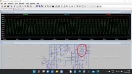
Here is the sim with a simple PSU added. You can see the ripple on the rails and the rails are modulated by the amps output which is delivering around 55 watts into 8 ohms.
Here is the sim with a simple PSU added. You can see the ripple on the rails and the rails are modulated by the amps output which is delivering around 55 watts into 8 ohms.
Attachments
Sounds like a plan
Here is the sim with a simple PSU added. You can see the ripple on the rails and the rails are modulated by the amps output which is delivering around 55 watts into 8 ohms.
Thanks. I've just watched a few youtube vids on PS ripple and noise because some of this is a bit over my head!
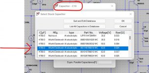
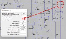
But I'm getting to grips with itI know using LTspice is a lot to grasp in one go When looking at ripple currents such things as wiring resistance and transformer output resistance make massive differences. Also the caps are modelled as ideal in my sim but we can add more realistic parts. For example the 4700uF cap is just that, 4700uF theoretical cap whereas the real one has lots more going on beside.
It all depends on what you are wanting to look at. For frequency response and so on it doesn't matter, for power supply issues it does.
You can right click a part and try and find something suitable from the database or you can simply add typical values yourself.
When looking at ripple currents such things as wiring resistance and transformer output resistance make massive differences. Also the caps are modelled as ideal in my sim but we can add more realistic parts. For example the 4700uF cap is just that, 4700uF theoretical cap whereas the real one has lots more going on beside.It all depends on what you are wanting to look at. For frequency response and so on it doesn't matter, for power supply issues it does.
You can right click a part and try and find something suitable from the database or you can simply add typical values yourself.
Attachments
I've found some 6800 caps that are pretty similar on there, but other things such as diodes etc. I'm struggling to find good matches. Some of my diodes are different from stock, D5-D10 are UF4007 in mine. I've found some external component libraries that I'm going through to find better matches.
I followed the advice of some others on another site and changed the 1N4003 diodes to UF4003 a while ago, and recently to UF4007. Supposedly there might be some sonic benefits. I've also seen a lot of evidence against this, so I'm going to see if I can add the three and compare them in this. I might not be able to discern any difference in LT but it'll be good practice anyway.
I followed the advice of some others on another site and changed the 1N4003 diodes to UF4003 a while ago, and recently to UF4007. Supposedly there might be some sonic benefits. I've also seen a lot of evidence against this, so I'm going to see if I can add the three and compare them in this. I might not be able to discern any difference in LT but it'll be good practice anyway.
You probably won't see any differences in simulation with different models, at least not at the level of the simulations here. What you might find is that different models might actually not run well at all... one of the issues I was struggling with earlier with this 306 simulation. If it seems to be taking forever to run (look at the bottom left of the window) then there is a problem. Right click the workspace and select Halt to stop it running.
Yes, I've encountered this as well. It was strange, when I undid all of the changes I made and basically had all the components back to their original state (in the file you posted), it would still get stuck during the sim. So I just started over, and it's running well now.
How well does this program work with tube designs? Do you have any experience using it with tubes as components? I ask because I'm currently deciding which cathode follower design I want to use when I build a line stage.
How well does this program work with tube designs? Do you have any experience using it with tubes as components? I ask because I'm currently deciding which cathode follower design I want to use when I build a line stage.
I just got the replacement transistor through the post, and it's all working perfectly now! Not even the extremely low-level buzz/distortion I had right at the beginning. I can't thank you enough for all of your help, I really appreciate it.
I'm going to spend some time comparing this one which is completely stock apart from the 8200uF caps, to the one with the Dada upgrades. I might also look into bi-amping these (probably not mono blocking these like I mentioned previously).
I'm going to spend some time comparing this one which is completely stock apart from the 8200uF caps, to the one with the Dada upgrades. I might also look into bi-amping these (probably not mono blocking these like I mentioned previously).
Hi Mooly, do you mind if I ask you your opinion on another thing?
This was posted by someone on another forum re: Quad 306 upgrades/mods:
"The 2 x 22R resistors quad use are slightly out, if you want to perfect
the current dumping bridge use 27R and 30R for each channels r24 and r25
and move r35 ideally to the junction of r13 and L1 as was done in the 909
or if you are not that brave to the upper side of r13 as was done in the 606
Quad usually did the 606 mod when amps went in for service, removing
the original placement and adding the 10k resistor bridging the left and far
right leg of T3"
What do you think about this person's mods, particularly regarding the 2 x 22R resistors (R24 and R25), as this would be a quick one to do.
They also changed R17 and R18 (2.5W 560R wire wound) to 5-watt metal film type resistors.
I know any further mods on the Quad is just splitting hairs really, and it should probably be left as is, but I'm just curious as to what you think about these mods?
Honest answer... on the bridge balance and the 44 vs 57 ohm, the maths and theory are to complex for me to solve. Have a look through the attached old documents which are applicable although originally about the 405. They are interesting reading.
(I suspect that the reasons Quad choose what they did will have some solid technical merit backed up by measurement as well as theory. Perhaps interaction or less than perfect (which theory often assumes) surrounding circuitry influenced the decision based on real measured results)
The 560 ohm metal films would be a good option imo. Non inductive, stable, stable with temperature change. Its win win on that one.
Moving the 10k to different point is one of those mods that needs backing up with measured real world data. Its a classic sort of analogue tweak that might change 'something' but is better or worse, or better on paper or better subjectively... or both. Its an easy thing to try though. Just be sure to change only that one thing and give the amp a fair listen afterwards, perhaps for several days and see if you genuinely feel it is better, worse or the same.
Attachments
Thanks for sharing those docs, I'll have a read through them
What you about Quad's reasoning behind their component values choices is probably spot on, so I think I'll just keep it all as is. It sounds great as is, anyway.
I think I'll change those 560R resistors though, as I want an excuse to keep on tinkering and soldering
What you about Quad's reasoning behind their component values choices is probably spot on, so I think I'll just keep it all as is. It sounds great as is, anyway.
I think I'll change those 560R resistors though, as I want an excuse to keep on tinkering and soldering
Take care tinkering repeatedly with old (or any age for that matter) PCBs. Some mod. fanatics ruin their gear because they can't stop fiddling with parts types and values before the copper foil tracks lift and some serious, skilled repairs are needed. Quad boards are pretty good quality but they're unprotected and old now and that's a problem so don't push the mods until something breaks. It's quite disheartening when something good and of highest value in pristine condition, is brought to to its knees, so to speak.
The underlying problem is that the glue ages and then breaks down with renewed and repeated heat cycling, losing its bond strength and grip on both the foil and epoxy/glass fibre board. Then you have nothing but wispy pieces of foil which tear away all too easily. Let's just say; it's not something you would knowingly accept in a product you wanted to buy
The underlying problem is that the glue ages and then breaks down with renewed and repeated heat cycling, losing its bond strength and grip on both the foil and epoxy/glass fibre board. Then you have nothing but wispy pieces of foil which tear away all too easily. Let's just say; it's not something you would knowingly accept in a product you wanted to buy
Last edited:
I think I'll change those 560R resistors though, as I want an excuse to keep on tinkering and soldering
Sounds like a plan.
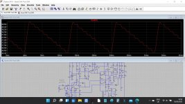
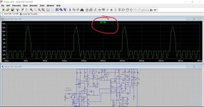
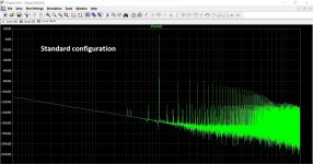
For curiosity I tried the simulation with the 10k mod vs original and then with the bridge mod vs original. No real differences in simulation.
Image 1 is original.
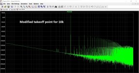
Image 2 is the 10k
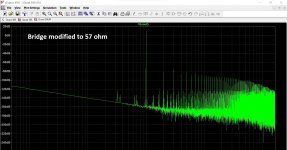
Image 3 is the bridge.
You need to look at the amplitude of the main harmonics.
Things like the 10k might even be more related to how the amp behaves at start up and shutdown as much as anything else (noises, thumps etc).
The maths of the bridge is extremely simple: L=RRC. But PJW's original article above states that even a large imbalance there only has a very small effect on distortion.
EJP
So did Quad make some error in the original design? Have you worked the optimal values out?
Attachments
Take care tinkering repeatedly with old (or any age for that matter) PCBs. Some mod. fanatics ruin their gear because they can't stop fiddling with parts types and values before the copper foil tracks lift and some serious, skilled repairs are needed. Quad boards are pretty good quality but they're unprotected and old now and that's a problem so don't push the mods until something breaks. It's quite disheartening when something good and of highest value in pristine condition, is brought to to its knees, so to speak.
The underlying problem is that the glue ages and then breaks down with renewed and repeated heat cycling, losing its bond strength and grip on both the foil and epoxy/glass fibre board. Then you have nothing but wispy pieces of foil which tear away all too easily. Let's just say; it's not something you would knowingly accept in a product you wanted to buy
I think I'm going to heed your advice. I noticed the other day that the foil around one resistor leg is almost completely gone on one of the quads, there must be just a little bit left where the solder is holding on to. I think I've pretty much finished up with everything on that one, though.
44Rx560Rx47F/1000000000000=1.158uH. Using 1.5uH => R=56.9, but you have to allow for some series R in the inductor. It's certainly not complex.Sounds like a plan.Have you worked the optimal values out?
Thanks. Things such as series R for the inductor in both the bridge and the feedback return were an unknown to me. In the sim I used 0.08 for the bridge L and 0.4 for the feedback L as guestimates and it does make a significant difference to the distortion result.
I would guess that Quad would get the basic circuit configuration sorted and then tweak the "easiestly tweakable" parts to get the best measured result, and those parts would be resistors.
Interesting
I would guess that Quad would get the basic circuit configuration sorted and then tweak the "easiestly tweakable" parts to get the best measured result, and those parts would be resistors.
Interesting
Sounds like a plan.
For curiosity I tried the simulation with the 10k mod vs original and then with the bridge mod vs original. No real differences in simulation.
Image 1 is original.
Image 2 is the 10k
Image 3 is the bridge.
You need to look at the amplitude of the main harmonics.
Things like the 10k might even be more related to how the amp behaves at start up and shutdown as much as anything else (noises, thumps etc).
So did Quad make some error in the original design? Have you worked the optimal values out?
Interesting, well, I think I'll leave them as they are. They've had enough messing around with over the last few weeks! I think I'll put this tinkering energy into something more useful... I need to proper line stage for these amps, and not just the pre-outs from a headphone amp, so I'll go on to making that next.
Thanks again for all of your help.
Last edited:
- Home
- Amplifiers
- Solid State
- Quad 306 buzz in right channel