Is there going to be much actual audible difference between an amp that has a THD of 0.03% and one that 0.09%
I have read up on this and it says at 10% it tends to become audible
the amp i have just repaired ,the NAD 3030 has a spec of 0.09% but it sounds supurb, ive not ramped it right up yet (got to wait till the neighbours go out") )
)
at realy low volume there is no distortion at all.
up against my current unit im using NAD 3240PE which i think is a realy good unit, it doesnt sound much different, if anything its a bit more mellow, a bit less 'bright'.
i think i have a good ear, i had them tested just over a year ago after i had an ear infection and according to what they told me after my ears are as good as a 25 years old, whch is suprising given the volume of noise they have put up with over the years
but is there much difference between 0.09% and 0.03%?
I have read up on this and it says at 10% it tends to become audible
the amp i have just repaired ,the NAD 3030 has a spec of 0.09% but it sounds supurb, ive not ramped it right up yet (got to wait till the neighbours go out
) at realy low volume there is no distortion at all.
up against my current unit im using NAD 3240PE which i think is a realy good unit, it doesnt sound much different, if anything its a bit more mellow, a bit less 'bright'.
i think i have a good ear, i had them tested just over a year ago after i had an ear infection and according to what they told me after my ears are as good as a 25 years old, whch is suprising given the volume of noise they have put up with over the years
but is there much difference between 0.09% and 0.03%?
0.03% is -70.5dB, 0.09% is 61dB, so a possibly detectable difference given the ear can sense
spurious tones at those levels below a carrier. But you need to chose careful test tones to make the difference audible in practice, such as 3kHz spur on 100Hz signal.
I've done some experiments and can detect a 7th harmonic of 100Hz if switched on and off abruptly down at -65dB, using headphones (speakers would probably mask this with their own distortion).
On general speech or music it would probably not be spottable, but most likely for electronic music which can resemble test tones at times (!).
Actually one case that can crop up in electronic music is two strong high frequency tones intermodulating (could even be ultrasonic), and the ear can be very able to spot a low frequency intermodulation product from these as the ear's sensitivity drops at HF to mask the originating tones, but is very sensitive to the lower freqeuncy of the product.
Last edited:
0.03% is -70.5dB, 0.09% is 61dB, so a possibly detectable difference given the ear can sense
That's also my experience.
For crossover distortion, 0.1% THD can be noticeable, if you play a pure sine wave tone.
With real music, usually I cannot tell.
i always find things like some stringed instruments and particularly piano produces the most distorted sounds
Piano tends to be very revealing of IMD - because the spectrum is very rich. It’s not just the harmonic content - even when playing a single note there is more than one fundamental tone present. Think about it - the key hits multiple strings, all slightly stagger tuned. Then the sounding board has its own resonances that this tries to excite. Add intermods from the third thru infinity to this and it can sound anywhere from “fuzzy” to downright “staticky”. If your amp has too much crossover distortion, a piano will find it - even at much higher levels than the first watt. If you think an underbiased amp sounds bad with piano, try a class D amp with a long dead time. You’ll want to throw that one into orbit after 5 minutes with piano music.
i always find things like some stringed instruments and particularly piano produces the most distorted sounds
I pick it up mostly in choral works.
A good working hypothesis is that an excellent studio microphone (say Nuemann U87- which could be used on piano or choir) can have a S/N ratio of about 80db- so I think that if the THD is around 0.01% and the THD+N is 0.02%, then these aspects will be inaudible. Consequently any amp designed for and meeting those specs is unlikely have any other audible distorting characteristics. on just my 2 cents/pence
Makes sense if comparing 2 different amplifiers with the same speakers.
More So
If you have a lot of hours of listening time on said speakers.
In a A / B quick listening test
Most wouldn't notice I would assume.
Interesting that the recording process got brought up.
Having done many recordings over the years.
I would say Piano and Drums rank the highest in most challenging to record.
Likewise the source recording can include more room sound or instrument sound
depending how the mics were placed.
When talking about the microphone, the mic preamp, limiter or compression
and the recording media. Especially analog tape.
Source recording is likely well over .03 or .09 distortion.
And even more curious if the thermal characteristic of the speakers would be more audible
Say the difference between 1 hour or 3 hours of heat in the voicecoils
Doing live sound with a few hours of continuous music
The Subs would get spongy sounding.
Very noticeable, since I had countless hours of listening
and very familiar with my speakers
Last edited:
You might enjoy reading the following link:
Distortion In Power Amplifiers
How hard it is to improve will depend on what the cause is and the the type of amplifier.
I substantially improved my QUAD405-2 with an OPA228 op-amp swap, a gain reduction and a current source modification.
However that would not apply to my uPC1342V which is basically a Douglas Self Blameless type amplifier in an IC with external outputs. With the uPC1342V I was able to reduce the THD by 6 dB by dropping the gain by 6 dB. But then is it sufficiently stable now? (It had far more gain than I need for my DAC.)
I have a number of amplifiers where the THD is higher than it is supposed to be (or claimed in the specifications) and I wonder if poor quality clone or fake components were used. (Perhaps different/smaller transistor die that might have lower and much less linear current gain. Perhaps rather generic LF power transistors being labeled as high ft devices.) I bought a DAC that contained a fake NE5532 also. A genuine Ti 5532 improved the situation and then OPA1612, OPA2134 and OPA2228 were better.
Also I have bought a number of kits that had no provision to adjust the bias. In some cases changing that and adjusting the bias helped.
The best measuring kit I have bought is the MX50X2. That was not claimed to be the best but it measured the best. Many that were supposed to be better actually measured worse. However my MX50X2 were measured for THD after replacing the drivers and outputs with genuine and very well matched Toshiba 2SC5200N, 2SA1943N, TTC004B and TTA004B. That was necessary since one of the boards burned on up first power up and I suspect component quality and mismatch.
Last edited:
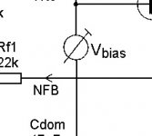
Look up the term "Vbe multiplier".
Consists of (usually) one bias transistor and a ratio of two resistors. (Rbc and Rbe).
The output voltage of the Vbe multiplier is equal to (1 + Rbc/Rbe) * Vbe
The bias transistor is often thermally coupled (mounted on) the heatsink for bias stability however there are variations such as for CFP outputs.
Is there going to be much actual audible difference between an amp that has a THD of 0.03% and one that 0.09%
I have read up on this and it says at 10% it tends to become audible
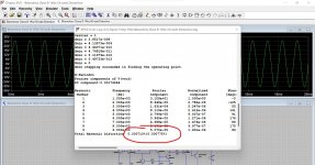
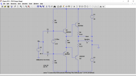
What I suspect you aren't grasping is that it is not just the raw numbers such as 0.03 vs 0.09 vs something else but also how that distortion is made up.
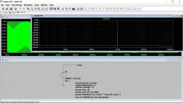
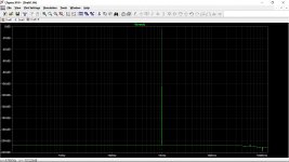
A pure signal source such a sine wave will have just a single frequency component to it such as in the first two images. This is just a 1k sine but the sim has been configured to show super high precision. There is just a single 'spike' at 1k showing the signal. There is nothing else. There is no distortion to this one. It is pure.
When that signal is fed to an amplifier (real or simulated) the amplifier adds its own unique mix of distortion. All amplifiers distort in some way.
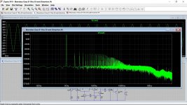
This shows the output of the popular Blameless Class B amp at full output. Notice all the extra harmonics at 2kHz, 3kHz and so on. The make up (the relative amplitudes of one harmonic to another) is what can appear to give an amplifier its own unique character.
It looks bad but the raw numbers show the total distortion is very low.
An amp like your NAD has a single ended input stage and the make up of distortion would be quite different.
So the actual % level doesn't always tell us what an amp will sound like.
Attachments
i take it then, in the 3rd simulation shown on here, and the term harmonic distortion is not nessesarily what is, or at all heard directly but that of what is generated in the components etc that eventualy could/can be heard as some kind of actual audible distortion.What I suspect you aren't grasping is that it is not just the raw numbers such as 0.03 vs 0.09 vs something else but also how that distortion is made up.
A pure signal source such a sine wave will have just a single frequency component to it such as in the first two images. This is just a 1k sine but the sim has been configured to show super high precision. There is just a single 'spike' at 1k showing the signal. There is nothing else. There is no distortion to this one. It is pure.
When that signal is fed to an amplifier (real or simulated) the amplifier adds its own unique mix of distortion. All amplifiers distort in some way.
This shows the output of the popular Blameless Class B amp at full output. Notice all the extra harmonics at 2kHz, 3kHz and so on. The make up (the relative amplitudes of one harmonic to another) is what can appear to give an amplifier its own unique character.
It looks bad but the raw numbers show the total distortion is very low.
An amp like your NAD has a single ended input stage and the make up of distortion would be quite different.
So the actual % level doesn't always tell us what an amp will sound like.
Any additional frequency component the amplifier generates from the pure input signal is called harmonic distortion. So if you apply 1kHz and the amplifier generates an output at 3kHz then it is producing 3rd harmonic distortion.
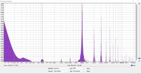
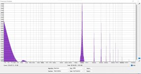
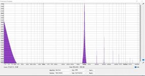
You might like this You can record the output of simulations, not just simple ones like here but also simulations of complete stereo amps playing music.
So this is the classic output stage with normal, low and then no bias. Each MP3 file plays for 10 seconds and each should sound very different. The levels have been normalised to be the same.
(had to put those in a zipped folder, the option to add MP3 to the forum has disappeared)
Each image shows the audio file looked at in Audacity (free program) and shows the spectrum of harmonics. Ignore all the very low frequency stuff which is an artefact of the laptop sound card.
You might like this
You can record the output of simulations, not just simple ones like here but also simulations of complete stereo amps playing music.So this is the classic output stage with normal, low and then no bias. Each MP3 file plays for 10 seconds and each should sound very different. The levels have been normalised to be the same.
(had to put those in a zipped folder, the option to add MP3 to the forum has disappeared
) Each image shows the audio file looked at in Audacity (free program) and shows the spectrum of harmonics. Ignore all the very low frequency stuff which is an artefact of the laptop sound card.
Attachments
Any additional frequency component the amplifier generates from the pure input signal is called harmonic distortion. So if you apply 1kHz and the amplifier generates an output at 3kHz then it is producing 3rd harmonic distortion.
You might like this
So this is the classic output stage with normal, low and then no bias. Each MP3 file plays for 10 seconds and each should sound very different. The levels have been normalised to be the same.
(had to put those in a zipped folder, the option to add MP3 to the forum has disappeared
Each image shows the audio file looked at in Audacity (free program) and shows the spectrum of harmonics. Ignore all the very low frequency stuff which is an artefact of the laptop sound card.
that wasnt done in spice though was it? you can very MUCH hear the difference
the third one, sounds quite dull in comparison to the first,which is too bright and has a sharpness to its edges, almost grating
Since, an amplifier most probably uses negative feedback, it is very tricky to modify its circuit without affecting stability. Sometimes, a swap of an output transistor with a more accessible and modern one, results in a vigorously oscillating amplifer which can destroy itself in half a minute. Therefore, any modifications, irrespective of how small they are, have to be done, keeping in mind, that an amplifier must remain well behaved, such that, it does not start oscillating on its own.
To improve the distortion figure there are various standard steps which can offer some hope, although great caution has always to be exercised.
a) current sources to feed the constant current to an input stage's differential pair
b) current mirrors as the load of input differential pairs.
c) a Miller capacitor at the VAS. This is a must and careful selection can have appreciable lowering of distortion
d) a constant current source as the load for the VAS
e) biasing the driver stage so that the output stage conducts an idle current of about 10mA per power transistor. This only applies to Class AB amplifiers.
f) Adding a buffer stage between the VAS and driver stage. The buffer, being an emitter follower, should have a very minimal impact on the VAS, thereby causing a very minimal VAS disruption. This method is usually only reserved for very high power PA amplifiers.
The following apply as measures to protect an amplifier from injection of foreign signals:
g) using extra power supply filtering for the input stage and VAS
h) protecting the input stage from stray magnetic fields from the mains transformer
i) using a super regulator to completely eliminate the power supply ripple
j) using a star earth connection for the input stage
k) using a low resistance, around 10R, between the power ground and signal ground. This tames down earth loops.
Note:
Thanks to Mooly and many others, I learnt all these thanks to these fora. Electronics is an elusive technology, experience and a deep personal humility to admit to oneself past errors, are assets without which, improvement is next to impossible.
- Home
- Amplifiers
- Solid State
- Amplifier THD