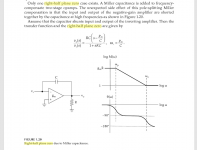
I'm playing around with a circuit idea for a poweramp front-end, but thought I'd try examining it as an opamp to understand it better. And now I'm stuck trying to solve an instability at 11 MHz when operated as a unity lo-pass inverter. I'm at a loss. I can see how changing the values of R4 and R22 change the ring, but I don't see how to squelch it. It seems to be acting as a short from the VAS down to the p-jfet on the input. In a way, if I avoid letting this freq into the circuit it won't ring, so maybe there really isn't a problem here... or not.

View attachment test inverter HV.asc
View attachment test 60x HV.asc
View attachment fetopamp2_hv.asc
View attachment fetopamp2_HV.asy.txt
View attachment test inverter HV.asc
View attachment test 60x HV.asc
View attachment fetopamp2_hv.asc
View attachment fetopamp2_HV.asy.txt
Last edited:
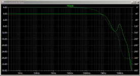
Missing symbols (suffix .asy) prevent me from reading your schematics. However the closed loop frequency response plot just might suggest that you accidentally have a right half plane zero at an uncomfortably low frequency. Bob Cordell's textbook 2nd edition calls this a "feed forward zero" and discusses it on p.237. Two ways to mitigate this, might include (i) decrease the compensation capacitor {and the IPS gm!} until you get a Ccomp less than 47 pF. Now the right half plane zero is moved to such a high frequency that it can be neglected; (ii) placing a resistor R2 in series with Ccomp, whose value is equal to or greater than 1/gm of the transimpedance stage. Might want to do some serious googling on the topic.
Here's a snip from a web page that I grabbed, four years ago.
_
Here's a snip from a web page that I grabbed, four years ago.
_
Attachments
Are you using a discrete opamp made by someone else or one of your own design? Can you post a screen shot of the schematic?
Many discrete opamps made by others have a -40 dB/dec rolloff in their open-loop amplitude response. They're then compensated (usually with a phase lead/lag compensation circuit) for stability at unity gain. Unfortunately this means that they're not stable away from unity gain. This, unfortunately, includes a gain of -1 (due to the 6 dB feedback factor).
And, yep. As Mark points out RHP zeros can be nasty.
Tom

It's probably missing this redraw of an nmos as depletion-mode
View attachment ndmos.asy.txt
Bob Cordell's textbook 2nd edition calls this a "feed forward zero" and discusses it on p.237.
I have his book. I'll jump right there. Thanks for the ref

I'm thinking you'll want a Miller compensation cap on the CB junction of Q4 rather than all the way from the output (which I'm assuming you're doing). I wouldn't want to include the output stage in that Miller feedback loop. If you have the headroom, you could also look at adding an emitter follower in front of Q4. Cordell writes about that as well.
I notice that you use a lot of diodes and LEDs for biasing. Beware that you're playing quite a few temperature coefficients against each other that way, which could result in unpredictable behaviour. I would include a couple of simulations at elevated temperature to check for that. I'm not saying that it is or is not a problem in your circuit. It's just something I'd look for.
Tom
Last edited:
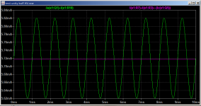
It works. Neg swing into load starved of current.
Dude! I think I see it. I'll have a look tomorrow when I have a clear head, thanks
It works. Neg swing into load starved of current.
Yeah, the CCS was falling on its face up around 100KHz and above. This is a bit better with just two more parts and conserving the LED ref that's already there. It just has to have 15mA idle or so which is 2 1/4 watts for each output device.

(rename *.asy.txt to *.asy)
Attachments
Last edited:
I am not sure about the context of your solution. The DC offset is very variable. Also keeping everything in one diagram as I did, is far easier to work on and understand. This is not a big circuit.
There is a fundamental issue with the output stage not transitioning to class B. You should separate the driver with output stage and work on this separately.
There is a fundamental issue with the output stage not transitioning to class B. You should separate the driver with output stage and work on this separately.
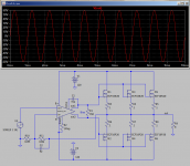
I'm so close I can taste it. Unity gain buffer almost working! A 9MHz RHZ whoopsie to find and solve next.
Attachments
There is a fundamental issue with the output stage not transitioning to class B. You should separate the driver with output stage and work on this separately.
It seems to be doing exactly what I want. The bottom stays stable at a set current leaving the top to do the swinging. Change the boost to increase the quiescent point
Attachments
I'm so close I can taste it. Unity gain buffer almost working! A 9MHz RHZ whoopsie to find and solve next.
When you get to university 3rd year EE they'll show you how to analyze open loop frequency response plots. Then you'll learn how the pure-symbolic stability equations can be mapped into rules of thumb for mostly-second-order systems. You'll find out why engineers and datasheet writers and even Jim Williams himself, focus so much attention upon "phase margin," among other thibgs.
There is a fundamental issue with the output stage not transitioning to class B.
Here's what I think you're looking for
Attachments
When you get to university 3rd year EE they'll show you how to analyze open loop frequency response plots. Then you'll learn how the pure-symbolic stability equations can be mapped into rules of thumb for mostly-second-order systems. You'll find out why engineers and datasheet writers and even Jim Williams himself, focus so much attention upon "phase margin," among other thibgs.
Jim is my hero. I saw him give an AES talk about the Hewlett-Packard oscillator about 2006. I'm still sad about his passing
- Home
- Amplifiers
- Solid State
- Discrete opamp instability help needed