Hello Tibi,
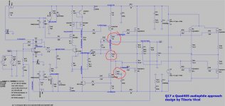
The extension of the Q17 by output stages with MosFET FQA leads to an increase in switching faults of the output drivers. As the Q17 is operated at the class B border, the deficits are increasing, which is why nobody wants to build class B.
Now there is the problem that increasing the switching voltage of the output transistors - as you suggest with a reduction of R10 and R13 - leads to destabilisation of the amplifier circuit. Increasing R11 and R12 is less critical, but not without problems. Since the installation of capacitors as damping of the driver transistors is a crutch, I have tried everything possible for a very long time. Finally, I ended up with 47k ohms to ground. With 100k Ohm, the simulation is still not ideal in all cases. That's why I had to lower the value further. So with the increase of R11 and R12, as well as the additional resistor, I get simulation results that can be compared with your Singel model.
Regards Tim
Attachments
")
Hello,
I was looking at the diagram of the version with 3 pairs of power transistors. I would have a suggestion for the power supply of the circuit on the PCB board.
Instead of putting a single large capacitor at the input of the power circuit, we replace it with a smaller one of 1000uF and we add a 470uF/100nF duo at the foot of each 46N15 and 36P15. Another 1000uF/100nF duo is also added to the "small signals" part (before Q5 and Q6) to supply this part.
What do you think ?
Incidentally, I would have liked to know the consumption in Amp per rail of the circuit with 3 pairs. For a 60v supply.
Cheers,
Stef.
Attachments
Hello!
I think there is a misunderstanding in what I wrote. I wasn't talking about the power supply for the amp board (or two boards if stereo box). I was talking about decoupling capacitors on the PCB itself. Is there a reason to put 10,000uF on the PCB if you have a good power supply to power the circuit board.
Stef.
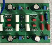
Decoupling each final transistor with a dedicated large cap and a MKP improve amplifier stability and response in medium-high.
Having large capacitors near output stage make sense and in fact this is the way many high-end amplifiers are designed.
AlexMM and Sorin Q17 PCB's are designed such way.
DanZup have started to mount AlexMM pcb and will have some feedback in the coming days.
However, sourcing quality parts is harder by each day.
Regards,
Tibi
Based on what calculations? How much track resistance are you expecting between the site of the 1000uF and your proposed 470uF?I thought rather to reduce the background noise and provide a reserve of energy as close as possible to the power transistors.
These values are only examples which have no theoretical basis for calculation for the Q17. I am talking about the principle of decoupling capacitors on the PCB instead of a single large capacitor which seems useless to me if we have a good power supply. As, moreover, Tibi has just spoken about it.
Stef.
Stef.
However, sourcing quality parts is harder by each day.
For those who are interested, I found Wima MKP10 IN STOCK at this seller.
1UF 250V MKP10 (C7)
WIMA – condensateur audio 22MM, 1UF 1.5UF 3.3UF 4.7UF 5.6UF 15UF 250V 400V 160V 63V 100V, rouge, 105/250v, MKP10 MKP4 | AliExpress
100NF 250V MKP10 (C17)
WIMA – film Audio MKP10, 15MM, capacite 100NF 120NF 180NF 220NF 250V 400V 630V 160V MKP X2 V V V, MKP4 MKS4 MKS10 P15 | AliExpress
Outage at Mouser and others larges distributors + minimum order.
Cheers,
Stef.
Hello Jan,
I'm sure the layout will play a part, but the other is my extremely high standards for precision playback, my extremely clean resolving DACs, and also the resolution capabilities of my speakers.
I just ordered new PCB, so I can test out how much a perfect result can be achieved by the layout and possible extensions of the basic circuit of the Q17.
Regards Tim
Hello,
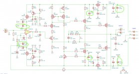
I was looking at what it was possible to remove as component on the base circuit to save space (to use better resistors at some place, but bigger resistors).
Do we really need all those 100nF capacitors?
Electrolytic capacitors now have so much with low ESR (was not the same 30 years ago) that I'm not sure this is useful and in addition small film capacitors in parallel with the electrolytic capacitor inductance can create an oscillating circuit.
An opinion?
Stef.
Attachments
Last edited:
- Home
- Amplifiers
- Solid State
- Q17 - an audiophile approach to perfect sound