I know many people who own Quad405 amplifiers are following this thread looking to improve or upgrade their amplifiers. I was asked on PM if Saligny Standard can be used as a drop in replacement for the standard rectifier in original Quad's.
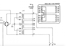
Short answer is: not with Saligy Standard, but this can be done with Saligny HVHF Custom. This is due Quad405 make use of a centre tap full wave rectifier.
Long answer is that it is possible an implementation with two Saligny Standard and some "arrangements" on transformer secondary windings.
These are:
- disconnect 6A, 7A, 6B and 7B from GND
- disconnect 6A from 7A
- disconnect 6B from 7B
- connect 6B with 7A
Now you have two separate secondary windings, 5B&7A and 7B&5A, that may be used same as in the power supply schematic described in the beginning of this thread.
Regards,
Tibi
Sorry, I know this is not related to this thread, but I do not want to open another one just for one post.
Attachments
Hello Tibi,
I can now report on the impressions of the first test listeners. All listeners connected the amplifier to different speakers and had to compete against amplifiers in the 1,000 to 8,000 € class. In the disciplines of stage imaging, clear detailed reproduction and bass performance, none of the amplifiers available for comparison could match the Q17. Of course, some amplifiers have the illusion of more bass compared to the Q17, but always at the cost of precision and loss of midrange performance.
Even a lover of the soft detail-reduced sound of an Accuphase was very impressed and confirmed the long-term listening ability of the Q17.
Today we had a music afternoon where the Q17 played rock at a higher volume for 3 hours. It was a great experience because I provided small 3-way speakers with 12-inch Oberton bass that projected a realistic drum sound into the listening room, so that the floor resonated with the corresponding bass attacks. The amplifier got a little warm, but nothing more.
Conclusion: An all around successful amplifier that offers music lovers an unknown realistic sound reproduction.
Regards Tim
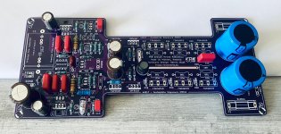
I'm going to run a small batch of Q17 power supply PCB.
I'll order 20 pcb's @ JLCPCB.
Those interested to get a board or two. Please let me know by email at office at evotronix.eu
Price per PCB will be 15euro and will be sold only together with Saligny Standard rectifiers.
If you are not OK with board price, or the fact you need to buy Saligny, than I have attached gerbers and you may order by yourself.
Regards,
Tibi
Attachments
Hello,
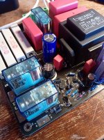
I have built the switch-on delay and loudspeaker protection circuit and realised that I have an error in the layout. The pin assignment of the MPSA06 is reversed, see picture.
Otherwise the circuit works.
Due to the slow transient response of the Q17, C3 can be chosen even larger. 150 uF to 220 uF are also possible. With 100 uF the speaker delay takes about 7 seconds.
Regards Tim
Attachments
 .
.
Hello,
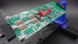
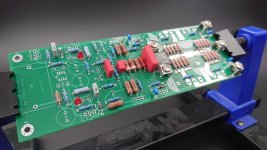
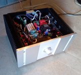
I have now set up a pair of Q17 Power with the additional output stages.
For the first switch-on - great!
In bridge mode my multimeter shows me 0 mV DC offset, which is remarkable.
In bridge mode it plays flawlessly, but I haven't tested it extensively.
In stereo mode it also plays well, but I didn't turn it up all the way because I don't want to destroy my PA speakers (small tops with 10" drivers).
The amplifier seems to have a new problem, it starts to scratch after a while, as if a resistor is overloaded. I will try to find out the cause of the problem. What's strange is that it always disappears first after switching on and then appears after a few minutes of playing, and only on one channel (it's not the speaker and not the music source either).
Now new for me is the +-50V the amp gets, now also via two active rectifiers with the 600 Hz controller chip.
I hope to do the comparison with the normal Q17 on Sunday and have the little problems fixed by then.
Regards Tim
Attachments
Well my boards are ordered, special thanks to Mircea from KDMaudio for the files.
Much appreciated !
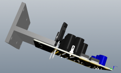
Will start to order spares, and the chassis is build from scratch.... let's see how this work out, I still have to turn down a transformer for +-60V, sadly only 1 supply for both channels but it should work OK.
I really enjoy these builds.
Regards
Much appreciated !
Will start to order spares, and the chassis is build from scratch....
let's see how this work out, I still have to turn down a transformer for +-60V, sadly only 1 supply for both channels but it should work OK.I really enjoy these builds.
Regards
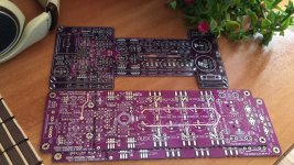
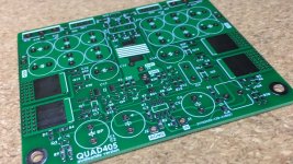
Hi, I found this discussion very interrested because I am refurbishing Quad 405 at the moment. The original PCB’s are quite bad shape, so I am planning the next move now.
These original size boards could be interresting option. Can I order these from some of you?
Br. Jani
These original size boards could be interresting option. Can I order these from some of you?
Br. Jani
- Home
- Amplifiers
- Solid State
- Q17 - an audiophile approach to perfect sound