Gentlemen,
Do we have a little high-powered one designed with more number of Output transistors ?
Regards,
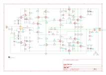
Something like this. PCB coil need to be re-dimensioned or use a normal air coil.
Regards,
Tibi
Attachments
Now a few words about the construction:
I have changed the layouts of Tibi, so that I can install especially the components of Reichelt and a Dip8 slot for my OPAs. I solder the SMD components on carriers so that I can plug them. Because I ordered the wrong size of OPA1641, I couldn't try the OPA1641 and so I used OPA1611 for the amplifier.
For the board I had the problem that for my soldering iron with 1mm wide tip the solderpeds were much too small. Therefore I have now created the layouts with new footprints.
The first connection turned out to be unproblematic, I took a small 2x 24V transformer, which produces 2x 36V DC at no load. My cup electrolytic capacitors have a size of 20mF and can deliver a lot of current. Therefore I used only 470 uF capacitors on the board.
The first tones of the amplifier were still too flat for me, there was a lack of three-dimensionality in the performance. Since I realized that the 1uF capacitor in the feedback of the opamp is crucial for the sound, I put a tin foil capacitor there. After that I had much more detail, but when I turned up the volume it became tinny in the sound.
Since I have now extensively tested the simulation of Tibi and I knew that the OPA1641 provides stable results, the OPA1611 oscillates. Since this can only be heard with a capacitor, which also works in the MHz range, is now understandable. To eliminate this error I soldered in parallel to the R6 (100 Ohm against ground) 15nF FKP2 with 499 Ohm. I had designed this assembly on the basis of the simulation to further optimize the high frequency from 8 kHz. With this modification the amplifier played in all volume ranges.
Something else to the Reichelt components:
- the IRF are good, they both seem to be from Vishay, the characteristics are clean.
- the BS250s are not great, two my component tester didn't detect, so I threw those two away. These components are missing half the plastic housing, so you have to be careful not to install it backwards.
- the other semiconductors I would want to rate as "normal", these were without much scatter, or abnormalities.
Since the first pair of amplifiers is a test setup that I also only mounted on a heatsink, and I can't get it into a case that way either, I continued to develop the board layouts, with very large solder pads. 
Here is my current version as a Gerber file. I don't think the KiCad file are useful, as these are tied to my modified database, and so would have to look different in conjunction with another database on another PC.
Here is my current version as a Gerber file. I don't think the KiCad file are useful, as these are tied to my modified database, and so would have to look different in conjunction with another database on another PC.
Attachments
Hello,
I am very impressed by the acoustic performance of the amplifier. The way it plays precisely and very emotionally is truly a rarity. Tibi is not exaggerating when he writes that this is a great circuit.
I have therefore further developed the board layout, for installation in aluminum housing. To simplify this, the board is now a little larger, but the amplifier fits on a wall space of 80 x 180 mm. I moved the Mos FET even further inwards. A two-sided labeling I have spared me this time. Everyone has to decide for himself which resistors he wants to mount on the backside if he uses this layout.
The board is supplemented with another place for a second pair of output transistors. I did not use source resistors, but drain resistors. In the last layout I reduced the distances between the wires very much, this is now corrected, they are now 0.6 mm, so the board should be safe up to 100V.
Another place is provided for a large audio MKP, this would be installed parallel to the C2 100uF electrolytic capacitor. So you can influence the behavior in the lowest frequencies as well as the feedback / DC servo. Whether this is useful or not, I will report as soon as I have the boards.
Regards Tim
Attachments
Yes,Tim the pleasure of listening such a precise yet musical amplifier make me also so happy everyday. Will modify soon my amplifier to the transistors Tibi recomend in this thread FQA 36 and 46 and get out actual SK and SJ finals. Will keep You posted about.
Last edited:
Hello Tim,
I'm glad you like the amplifier sound. This all that matter.
Using drain resistors in final stage will not help to equalise operation of the mosfets. In fact you will increase output impedance and loose power. Usually these "ballast" resistors are used in source in order to correct differences in Vgs and bring all transistors to close operation point. In a class A or AB amplifier you need these source resistors, in order to dissipate power over all final transistors and make them operate at same operation point. In our case the amplifier is biased very close to class A, with very low Ids. You may shunt drain resistors and parallel two pairs without source resistor. One mosfet will open before the other, so you may want to have them from the same manufacturer lot, or to match them with very close Vgs. The advantage of doing so is that you get even lower output impedance with better control over complex speakers.
Regards,
Tibi
Last edited by a moderator:
Hello Tibi,
I understand what you write, but I don't understand the electronic context. The opening behaviour of Vgs is controlled by the gate resistors. A source resistor that is several times smaller than the gate resistor has no influence on Vgs, does it?
But anyway, I can use wire bridges and pair the mosfet, that's the ideal variant in any case.
Regards Tim
Although I have not yet understood why a very low resistor can shift the operating point relative to the other MOSFETs so that they operate syncronously, even if their parameters are not the same, I have understood that a drain resistor is useless.
Therefore there's another board layout, this time with source resistors.
I think this board fulfills many qualities:
Very large solder pads, a good boardsize - the rather cheap case: BRZHIFI BZ2409 should be sufficient for the amplifier - the traces are optimized in width and distance to each other, the ground planes are everywhere and the inductance of Tibi should be sufficient in double copper thickness - 70 um - .
What I expect with two outputs MosFet is that they can realize very high control of bass drivers. Many amplifier manufacturers advertise this, but only a few deliver an amplifier that can do it. The point, of course, is that this is always a borderline case of whether two output transistors are better than one. I think this is only the case if they have small tolerances to each other.
Attachments
Mosfet gate resistors, named also gate stoppers, are there to avoid any unwanted oscillations. The gate current is too small to have any considerable voltage drop over gate resistor in order to make a Vgs "balance" between transistors.
Now for the source balast resistor: is the same as you put several LED's in parallel. If you just put them without any series resistor, some will light brighter than others. To make them light at the same intensity, you need to add a resistor in series for each one.
Regards,
Tibi
Now for the source balast resistor: is the same as you put several LED's in parallel. If you just put them without any series resistor, some will light brighter than others. To make them light at the same intensity, you need to add a resistor in series for each one.
Regards,
Tibi
Hi Tibi,
In your Q17 documentation I read that the output stage (Q15-Q16) is biased "near to class A operation, requiring a large heatsink".
Can you indicate power dissipation of the output devices, based on approximately +/- 50 V supply? In other words: how much DC current is flowing through the output stage?
That will make clear how large the heatsinks must be, right?
Hi,
Well, not quite my words ...
Near class A is still in class B. Final stage will run in class B and maybe very slightly biased in A (few mA), depending on mosfet Vgsth=gate source threshold voltage.
To answer your question, the DC current trough final stage is so low that can be ignored.
However, they still require heatsink. Not a big one like a class A/AB amplifier. Anything over 200cm2/mosfet should be enough to keep them cool at room temperature.
More precaution should be taken on Q5 and Q6 who are running class A and dissipate ~3W each.
Regards,
Tibi
Last edited by a moderator:
- Home
- Amplifiers
- Solid State
- Q17 - an audiophile approach to perfect sound