What I see so far:
- You successfuly demonstrated the Gm doubling effect in bipolar class AB stages, and the impact of the bias. As expected, the "wings" are going through a minimum at optimum bias) then flattening out toward class A. This would explain the known class AB distortions vs. bias profile - distortions start high a zero (or very low) bias, then have a minima at the Barney Oliver bias, point, then increase a little (over biasing) then decreases asymptotic toward zero (class A).
- You successfully demonstrated one of the very few advantages of a CFP output stage - it needs low bias for the optimum distortions (that is, a minimum Gm doubling effect, minimum transconductance variation in post #4), therefore is able to run cooler than a double or the Locanthi triple. See Bob Cordell's book for an explanation. Otherwise, I agree the CFP output stages suck big times.
Not sure if such a complex setup is required for investigating the above, though, changing the bias and sweeping the input signal with various source impedance would achieve the same results, I believe. It would be very interesting to see a side by comparison between a double and a triple output stage, using your method.
Last edited:
Think about parasitic property of CFP ‘shoot through’, compare with operation of Krill amplifier output with h.f. Non-switching and reports that both amplifiers have superb treble.
I will test the CFP with higher resistors between the base and emitter of the power devices to make it switch off even slower. Will it make some sort of "ultra gentle non-switching class AB" or will it make a mess? Answer tomorrow.
Now that you have opened a huge can of worms, it's up to you to fix it, and provide workable solutions to linearize all that mess
Fingers crossed lol
Not sure if such a complex setup is required for investigating the above
To be honest, I'm not really testing the CFP, more like using the CFP to test the test setup, because its behavior is well known. So far it is delivering coherent results.
But what this is really about... it's the MOSFETs.
The spice models of BJTs are pretty nice, but for MOSFETs, well... I don't trust the models. Especially about the capacitance and how it varies with pretty much everything.
I would generalize your conclusions ("it sucks") to "any circuit where the drivers are allowed to partially drive the output".
So, for example, consider the darlington (the one with resistors R across the power devices base-emitter junctions, not the usual emitter follower OPS where the drivers do not touch the output node but are instead connected together with a resistor and a cap).
So, with this darlington, just like with the CFP, when one half of the OPS outputs a current that is lower than R/Vbe, but higher than zero, the power device turns off, but the driver is still running. So the current gain of this half of the output stage switches from the product of driver*power_device hFe's to just the driver hFe. Hence the huge swings in current gain.
Likewise for the huge swings in phase in the current gain, which strongly influences open loop gain and phase...
I expect the usual emitter follower OPS to exhibit a much smoother current gain transition in the crossover region, since it always has a driver and a power device active. It should basically be driver hFe multiplied by top device hFe on one side, bottom device hFe on the other, and a more or less smooth step. So, say perhaps a 20-30% variation, not 800%.
Also I think gm is not really relevant, as amps using fancy compensation like TPC/TMC are pretty much just current gain from the input to the output stage. So who cares what the voltage at the base of the drivers is, and therefore, who cares about gm. The fugly current gain is a much worse problem IMO.
> It would be very interesting to see a side by comparison between a double and a triple output stage, using your method.
Yes.
Member
Joined 2009
Paid Member
I would love if you could do my TGM8 output stage which is CFP with Class A B and C operation but it also operates inside a powerful gnfb loop.
One builder reported "My initial impression (mono only) is the same, the low frequencies are crisp and punchy - never heard anything quite like it. The treble easily rivals my 6L6 ultra linear push pull amp with Tango output transformers, plenty of air, no fatigue (also no apparent dumbing down of the sound!). Makes you realise why you loved audio in the first place!"
One builder reported "My initial impression (mono only) is the same, the low frequencies are crisp and punchy - never heard anything quite like it. The treble easily rivals my 6L6 ultra linear push pull amp with Tango output transformers, plenty of air, no fatigue (also no apparent dumbing down of the sound!). Makes you realise why you loved audio in the first place!"

The Rigol bugs have surrendered.
2 channel scope + some relays + python = 6 channel scope
View attachment 965875
Also I got a darlington in the mail. But just one. The PNP did not ship.
The bottom left and middle pictures, isn't that just Hysteresis, as in an output transformer?
The bottom left and middle pictures, isn't that just Hysteresis, as in an output transformer?
It's just the way a XY plot shows phase shift between voltage and current, which is normal as frequency increases.
This CFP shows terrible crossover spikes in some situations.
But do they appear in practice with real signals? I mean if it doesn't occur, who cares. It's like saying "OMFG this amp has bad clipping!" while you got 95dB/w speakers so it will never clip and the neighbors call the police above 2.83V RMS anyway.
The worst case happens when the highest di/dt of output current is not centered on zero, but at the edge of the crossover, when one device turns off. So, I set bias to 50mA, which means turn-off will be at 100mA. I set the output current DC offset to 100mA, so the AC output current wobbles around that, and I step frequency and amplitude.
With 50mA bias, there is plenty of static crossover distortion (from changes in gm and current gain), but there are no switching spikes. I'm not going to post ALL the graphs because they look similar, so here's a worst case / best case.


Dynamic crossover distortion (ie, nasty crossover spikes) do occur at frequency and current levels that definitely qualify as "audio", but not really as "music". For example, 240mA at 12kHz would probably be quite deafening. Here it is with 50mA bias:

With 15mA bias, same story but worse.


But do they appear in practice with real signals? I mean if it doesn't occur, who cares. It's like saying "OMFG this amp has bad clipping!" while you got 95dB/w speakers so it will never clip and the neighbors call the police above 2.83V RMS anyway.
The worst case happens when the highest di/dt of output current is not centered on zero, but at the edge of the crossover, when one device turns off. So, I set bias to 50mA, which means turn-off will be at 100mA. I set the output current DC offset to 100mA, so the AC output current wobbles around that, and I step frequency and amplitude.
With 50mA bias, there is plenty of static crossover distortion (from changes in gm and current gain), but there are no switching spikes. I'm not going to post ALL the graphs because they look similar, so here's a worst case / best case.
Dynamic crossover distortion (ie, nasty crossover spikes) do occur at frequency and current levels that definitely qualify as "audio", but not really as "music". For example, 240mA at 12kHz would probably be quite deafening. Here it is with 50mA bias:
With 15mA bias, same story but worse.
This is interesting, because some of the nicer amplifiers out there use a CFP arrangement, but they are more like a power "diamond buffer".
A couple of these would be the Nakamichi 620 power amp, and the Marantz 170DC / 300DC. They tend to be very smooth sounding. Maybe the situation is different in that arrangement? I can send you a schematic if you are interested, Just PM me your email address. These schematics are available easily on the internet too.
What would be ideal would be one you could test directly. Unfortunately I don't have time to replicate your test setup or I would test them for you.
-Chris
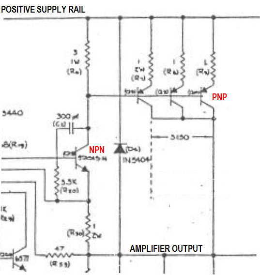
Here's the schematic of the Threshold S500 power amp with CFP output stage. It shows how they offered several different amplifier models, with different output power levels, just by increasing the number of parallel "current dumper" PNPs in the complementary feedback pair.
Full schematic in the .pdf attachment; partial schematic showing only the (first) CFP, here:
_
Full schematic in the .pdf attachment; partial schematic showing only the (first) CFP, here:
_
Attachments

This is interesting, because some of the nicer amplifiers out there use a CFP arrangement, but they are more like a power "diamond buffer". A couple of these would be the Nakamichi 620 power amp, and the Marantz 170DC / 300DC.
Thanks. I checked the service manuals on hifiengine: these are definitely not CFP ; they use diamond buffers and the Nak uses the 2 upside down drivers for bias thermal compensation. So they should work just like the standard Emitter Follower output stage.


Here's the schematic of the Threshold S500 power amp with CFP output stage. It shows how they offered several different amplifier models, with different output power levels, just by increasing the number of parallel "current dumper" PNPs in the complementary feedback pair.
This one is not a CFP output stage either... look how the collectors of the power devices are connected. In a CFP they would go to the emitter of the driver, but here they don't. They just dump current into the output, acting more like a current mirror with a lot of gain. This output stage is bascally a current feedback opamp. It's a big difference: in a CFP the drivers turn off almost at the same time as the power transistors, due to the feedback through the emitter resistor. In this design, they don't.
However, it's Nelson pass, so there are huge heat sinks, and the drivers run at around 200mA, plus 200-450mA total bias for the output transistors. So it's essentially a class A amp... They're not the usual "current dumpers" that are normally off.
Last edited:


Is the general principal of this analogous to the (old) effort of damping the mechanism in a CD player? That is, if all the servos arent working as hard to react to vibration in the first place, you'll hear that in the music?
The analogy being, in a design where the output stage drivers arent "struggling" so much to overcome your injected signals, you'll hear that when playing music into a speaker?
The analogy being, in a design where the output stage drivers arent "struggling" so much to overcome your injected signals, you'll hear that when playing music into a speaker?
Is the general principal of this analogous to the (old) effort of damping the mechanism in a CD player?
No. It's analogous to understanding why your CD player sounds better when the mechanism is damped.
I found the answer to that one by chance a long time ago by sticking some probes in a CD723. It's pretty straightforward. When the CD player vibrates, the actuator coils in the optical pickup are driven with corresponding current to keep the optics on track to read the disc. So it draws a current from the power supply that is a pretty good replica of the vibrations. Throw in a garbage quality power supply (CD723 lol) and basically, you stick a scope probe on the power rail, and when someone walks in the room, you see the trace wobble. This was faithfully replicated as jitter on the digital output, visible to the naked eye on the scope, so there was really tons of the stuff. An actual solution to this would be to make the actuator driver draw constant current by dumping unused current, like a shunt regulator. It would cost $1 and beat putting the player on a 50kg granite slab polished by virgins and anointed with green markers. But CD players are obsolete anyway, so who cares.
The analogy being, in a design where the output stage drivers arent "struggling" so much to overcome your injected signals, you'll hear that when playing music into a speaker?
It's not about "struggling", that's anthropocentric, transistors don't sweat (although they smoke sometimes). Basically, the rest of the amp has to correct the nonlinearities in the output stage (non constant Gm and current gain, etc) and its correction capability is not infinite, so might as well start with an output stage that has less defects.
Speaking of which, the two-face is out, and I've wired the old classic:
MJL3281 and MJL1302 with 0R33 emitter resistors.
I don't think a schematic will be required. They have 20R base resistors (to measure current) and are driven directly by the opamp on the test jig. I put in a TPA6120 composite so it doesn't care about having to output a little bit of current.
As explained before, these curves show the static transfer function, the low frequency 40Hz wave sets the current, and the high frequency wave allows measurement of the transfer function. Voltages and amplitudes are in the figure titles.
15mA bias


Bottom left, Gm: it is a bit underbiased (Gm dips in the middle)
Top right: current gain has a quite smooth transition between the two transistors, one has hFe ~ 100 and the other ~ 125. This is quite different and much better than the huge variations from the CFP or quasi-comp.
Top left: the current sharing plot is smooth, there are no sharp corners like in the CFP. High values of high-order derivatives (aka, sharp and pointy graphs) basically mean high-order distortion products. Smooth means low-order distortion products, which is better, easier to correct with feedback, etc.
Difference between the two plots is the signal frequency, so the current gain loses a bit of steam above 20k at low output current.
60mA bias
It's the same, but better.


This time it's close to optimally biased, but the gm curve can never be flat with BJTs, there is always a bump in the middle. However the current gain transition is wider, and therefore smoother.
Bias 120mA


It's still excellent. One of the transistors is faster than the others, so the curves look symmetrical at 12kHz, almost textbook perfect, and they lose symmetry at 48kHz.
Another way to look at the same data...


And the distortion on the output voltage depending on where we are in the waveform:

It is not worse than the CFP. In fact the CFP uses its feedback mostly to make a mess of high order harmonics, whereas the classic EF just works.
I'm going to put in some drivers.
MJL3281 and MJL1302 with 0R33 emitter resistors.
I don't think a schematic will be required. They have 20R base resistors (to measure current) and are driven directly by the opamp on the test jig. I put in a TPA6120 composite so it doesn't care about having to output a little bit of current.
As explained before, these curves show the static transfer function, the low frequency 40Hz wave sets the current, and the high frequency wave allows measurement of the transfer function. Voltages and amplitudes are in the figure titles.
15mA bias
Bottom left, Gm: it is a bit underbiased (Gm dips in the middle)
Top right: current gain has a quite smooth transition between the two transistors, one has hFe ~ 100 and the other ~ 125. This is quite different and much better than the huge variations from the CFP or quasi-comp.
Top left: the current sharing plot is smooth, there are no sharp corners like in the CFP. High values of high-order derivatives (aka, sharp and pointy graphs) basically mean high-order distortion products. Smooth means low-order distortion products, which is better, easier to correct with feedback, etc.
Difference between the two plots is the signal frequency, so the current gain loses a bit of steam above 20k at low output current.
60mA bias
It's the same, but better.
This time it's close to optimally biased, but the gm curve can never be flat with BJTs, there is always a bump in the middle. However the current gain transition is wider, and therefore smoother.
Bias 120mA
It's still excellent. One of the transistors is faster than the others, so the curves look symmetrical at 12kHz, almost textbook perfect, and they lose symmetry at 48kHz.
Another way to look at the same data...
And the distortion on the output voltage depending on where we are in the waveform:
It is not worse than the CFP. In fact the CFP uses its feedback mostly to make a mess of high order harmonics, whereas the classic EF just works.
I'm going to put in some drivers.
Dynamic results are also pretty good.
50 mA bias, 320mA current, 24kHz is very clean.

Got to go to 640mA at 80kHz for it to start to misbehave, and even then, these are not the sharp spikes of the CFP.

Pimping up the bias to 120mA helps a bit, but not as much as I'd thought.

The area highlighted by the arrow shows negative emitter current. This is the charges being sucked out of the base.

This happens after the transistor has turned off. It is simply due to the capacitance of the base, which still exists even when it is off. Although its value is lower when the transistor is off, the voltage swing on it is higher since it is no longer bootstrapped by the transistor itself. So it doesn't stop taking current, it is still there...
Unfortunately, all the graphs are AC coupled, so they do not show the actual zero on the base current trace. That was one of the SCPI Rigol bugs...
50 mA bias, 320mA current, 24kHz is very clean.
Got to go to 640mA at 80kHz for it to start to misbehave, and even then, these are not the sharp spikes of the CFP.
Pimping up the bias to 120mA helps a bit, but not as much as I'd thought.
The area highlighted by the arrow shows negative emitter current. This is the charges being sucked out of the base.
This happens after the transistor has turned off. It is simply due to the capacitance of the base, which still exists even when it is off. Although its value is lower when the transistor is off, the voltage swing on it is higher since it is no longer bootstrapped by the transistor itself. So it doesn't stop taking current, it is still there...
Unfortunately, all the graphs are AC coupled, so they do not show the actual zero on the base current trace. That was one of the SCPI Rigol bugs...
- Home
- Amplifiers
- Solid State
- Power amp OUTPUT STAGE measurements shootout