I've build a setup to do various kinds of measurements on transistors and amplifier output stages. In its current incarnation, the business end of it looks like this:

It has two states:
At idle, M1 M2 M3 are off, Q1 sets the Vce (or Vds) of the transistor under test (DUT), and it is biased with a 12mA CCS. A MCP9701A temperature probe soldered on a piece of copper sheet clamped on the back of the power transistor measures temperature.
To do a pulsed measurement, first the programmable positive and negative power supplies are set to the desired value ; the positive one sets Vce, and the negative one sets pulse current. Then M3 turns on, which applies Vce ; M1 or M2 turn on, which applies current to the transistor ; a few microseconds later, the microcontroller's ADC measures base current, Vbe, and the voltage on the emitter. Then it turns off the FETs, which returns everything to idle, waits a bit, and resumes stepping through the set values of voltage and current.
Temperature is stepped too: before the test is started, the transistor heats itself to 100°C using the same FET-switched current setting resistors as during the measurement. The transistor and temperature probe are wrapped in a bunch of paper towels, so the assembly slowly cools down to ambient temperature over a period of several minutes.
I'll spare you the rest of the details on the implementation.
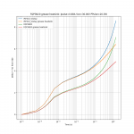
First experiment is an IRFP240. Instead of a short pulsed measurement yielding one data point (as explained above) here a 20W heating pulse is applied during about one second, during which Vgs is recorded.

This is pretty much the same as the transient thermal impedance. Junction temperature can be extracted from Vgs with a tempco of about 4-5mV/°C so here, it doesn't heat that much. 20W for 20ms results in about 1°C heating. It is linear with applied power.
"IRFP240" means just the naked transistor. Then it is attached to a small aluminium heatsink with various materials. The generic fiberglass loaded silicone silpad is absolute garbage, its thermal conductivity is only 2W/mK, which results in a transient response that isn't different from no heatsink at all. The transistor would have to heat until there is enough of a delta-T to have proper heat transfer. On the other hand, both the grease and the GELID GP-ULTIMATE (a thermal pad for discriminating overclockers) work extremely well.
In other words, the available one-second Safe Operating Area of the transistor would be a lot worse with the silpad. I like amplifiers that don't burst into flames, so SOA is important.
However the GELID pads are single use and fall into pieces when removing the transistor, so not really user-friendly. The keratherm pads on the webshop look like a good investment.
Another longer test, grease vs silpad:

I will test the effects of that on bias stability later...
To be continued.
It has two states:
At idle, M1 M2 M3 are off, Q1 sets the Vce (or Vds) of the transistor under test (DUT), and it is biased with a 12mA CCS. A MCP9701A temperature probe soldered on a piece of copper sheet clamped on the back of the power transistor measures temperature.
To do a pulsed measurement, first the programmable positive and negative power supplies are set to the desired value ; the positive one sets Vce, and the negative one sets pulse current. Then M3 turns on, which applies Vce ; M1 or M2 turn on, which applies current to the transistor ; a few microseconds later, the microcontroller's ADC measures base current, Vbe, and the voltage on the emitter. Then it turns off the FETs, which returns everything to idle, waits a bit, and resumes stepping through the set values of voltage and current.
Temperature is stepped too: before the test is started, the transistor heats itself to 100°C using the same FET-switched current setting resistors as during the measurement. The transistor and temperature probe are wrapped in a bunch of paper towels, so the assembly slowly cools down to ambient temperature over a period of several minutes.
I'll spare you the rest of the details on the implementation.
First experiment is an IRFP240. Instead of a short pulsed measurement yielding one data point (as explained above) here a 20W heating pulse is applied during about one second, during which Vgs is recorded.
This is pretty much the same as the transient thermal impedance. Junction temperature can be extracted from Vgs with a tempco of about 4-5mV/°C so here, it doesn't heat that much. 20W for 20ms results in about 1°C heating. It is linear with applied power.
"IRFP240" means just the naked transistor. Then it is attached to a small aluminium heatsink with various materials. The generic fiberglass loaded silicone silpad is absolute garbage, its thermal conductivity is only 2W/mK, which results in a transient response that isn't different from no heatsink at all. The transistor would have to heat until there is enough of a delta-T to have proper heat transfer. On the other hand, both the grease and the GELID GP-ULTIMATE (a thermal pad for discriminating overclockers) work extremely well.
In other words, the available one-second Safe Operating Area of the transistor would be a lot worse with the silpad. I like amplifiers that don't burst into flames, so SOA is important.
However the GELID pads are single use and fall into pieces when removing the transistor, so not really user-friendly. The keratherm pads on the webshop look like a good investment.
Another longer test, grease vs silpad:
I will test the effects of that on bias stability later...
To be continued.
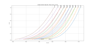
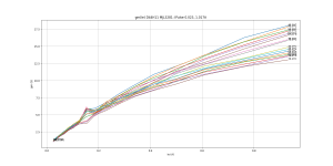
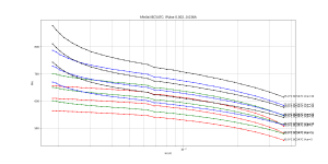
Alright. MJL3281 (BJT) vs IRFP240 (vertical FET) vs ALF08N16 (lateral FET equivalent to the EXICONs).
First, Ie vs Vbe. Note the software doesn't care if it's a FET, it labels everything with BJT pins.
MJL3281 is mostly here to test the test setup itself. It delivers the expected exponentials, with negative tempco.

IRFP240 delivers a nice square law, as expected, with negative tempco.

The lateral shows its null tempco point at around 100mA.

It is not possible to get these measurements without using pulsed method, because at higher currents self-heating introduces substantial errors.
Putting all of them on the same graph, the huge transconductance of the BJT is apparent in the steep slope of Ie(Vbe). The vertical FET transconductance is lower, and the lateral FET even lower.

This doesn't say how these will stick together with the complimentary transistor in crossover, that will be measured with the other part of the setup...
First, Ie vs Vbe. Note the software doesn't care if it's a FET, it labels everything with BJT pins.
MJL3281 is mostly here to test the test setup itself. It delivers the expected exponentials, with negative tempco.
IRFP240 delivers a nice square law, as expected, with negative tempco.
The lateral shows its null tempco point at around 100mA.
It is not possible to get these measurements without using pulsed method, because at higher currents self-heating introduces substantial errors.
Putting all of them on the same graph, the huge transconductance of the BJT is apparent in the steep slope of Ie(Vbe). The vertical FET transconductance is lower, and the lateral FET even lower.
This doesn't say how these will stick together with the complimentary transistor in crossover, that will be measured with the other part of the setup...
Okay, now, gm, or transconductance, which is d(Ie)/d(Vbe)... This is a derivative, so it ignores threshold voltage.
The blip in the curve a bit below 200mA is due to switching between the two current setting resistors, so it is an artifact.
Both the BJT and the lateral have gm dropping about 15% when heated to 75°C compared to 40°C. The vertical FET, on the the other hand, doesn't care, its gm doesn't depend on temperature at all.
The vertical FET's gm is quite proportional to current over a wide range.
The others, not so much. They behave like an exponential (BJT) or square law (Lateral FET) with a resistor in series. Thus the vertical FET should have the nicest crossover... we'll see.
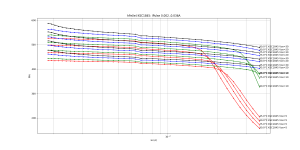
As expected, the BJT's hFe increases with temperature. The test current isn't high enough to get hFe droop at high current, but like all BJTs its gain also drops at low current.

If the input current required by the output stage is distorted, the non-zero output impedance of the previous stage means there will be distortion added to the output. This input current required by an output stage is the sum of base current due to hFe, plus the current required to charge the input capacitance of the transistors. So, something like Iout/hFe + Cbe dVbe/dt + Cbc DVout/dt.
Consider a signal of constant current slew rate going through the crossover. During the crossover, at low current, hFe drops, and gm also drops, which requires higher dVbe/dt, thus higher current due to the capacitive terms.
I wonder which part of the equation is worse ; will the FET win due to having no hFe, or lose due to uglier capacitance?...
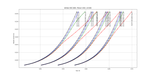
Now... about bias stability.
MJL3281 has the standard -2.5mV/°C Vbe tempco at low temperature, but at higher temperatures it becomes a bit worse.

IRFP240 exhibits roughly the same behavior, except the tempco is double that of the BJT.

However, at usual bias currents like 100mA, the BJT has 5x more transconductance than the FET, and what matters for bias stability isn't just the threshold voltage tempco, but its product with gm, which gives as a result the variation in bias current with temperature. So the urban legend that says "vertical FETs risk thermal runaway" doesn't seem to be based in facts...
The lateral FET has pretty constant tempco versus temperature. Tempco on current instead. That's what makes the zero tempco bias point possible.

Alright. I will test some more N devices (FQP3N30 and some TO220 BJTs) and report later...
MJL3281 has the standard -2.5mV/°C Vbe tempco at low temperature, but at higher temperatures it becomes a bit worse.
IRFP240 exhibits roughly the same behavior, except the tempco is double that of the BJT.
However, at usual bias currents like 100mA, the BJT has 5x more transconductance than the FET, and what matters for bias stability isn't just the threshold voltage tempco, but its product with gm, which gives as a result the variation in bias current with temperature. So the urban legend that says "vertical FETs risk thermal runaway" doesn't seem to be based in facts...
The lateral FET has pretty constant tempco versus temperature. Tempco on current instead. That's what makes the zero tempco bias point possible.
Alright. I will test some more N devices (FQP3N30 and some TO220 BJTs) and report later...
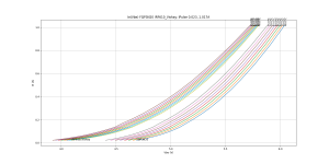
I had a FQP16N20 lying around. It's the TO-220 version of FQA19N20 that Mr Pass recommends.
FQP is the top group of curves on next graph. It has higher transconductance than IRFP240 while having also lower capacitance, which means easier to drive (higher Gm=lower Vgs swing, multiplied by lower capacitance, means lower drive current).

However... FQP is the bottom group of curves in next graph, which is tempco. It has much higher (in absolute value) tempco than the IRF, at low temperature -7mV/°C versus about -5mV/°C, but when it gets hot it gets much worse.

That explains why I had trouble with the bias on an output stage using these...
Also TO220 is not really suitable for an output transistors, unless you use a ton of them, and in this case smaller FETs with lower capacitance would work better. But can I resurrect EOL'd FQA19N20 by soldering the TO-220 version on a thick copper slug, to make a fake TO-247?

Unfortunately this is the only one I have and it's not coming off that chunk of copper, so I can't compare to a real FQP19N20.

Temperature was calculated from Vgs tempco. So, the answer is "meh": a TO220 soldered on a copper slug mounted on a heat sink without isolation does outperform the TO-247 with the garbage silpad, but that's not a fair comparison. In a fair comparison (both using grease), the real TO-247 wins.
FQP is the top group of curves on next graph. It has higher transconductance than IRFP240 while having also lower capacitance, which means easier to drive (higher Gm=lower Vgs swing, multiplied by lower capacitance, means lower drive current).
However... FQP is the bottom group of curves in next graph, which is tempco. It has much higher (in absolute value) tempco than the IRF, at low temperature -7mV/°C versus about -5mV/°C, but when it gets hot it gets much worse.
That explains why I had trouble with the bias on an output stage using these...
Also TO220 is not really suitable for an output transistors, unless you use a ton of them, and in this case smaller FETs with lower capacitance would work better. But can I resurrect EOL'd FQA19N20 by soldering the TO-220 version on a thick copper slug, to make a fake TO-247?
Unfortunately this is the only one I have and it's not coming off that chunk of copper, so I can't compare to a real FQP19N20.
Temperature was calculated from Vgs tempco. So, the answer is "meh": a TO220 soldered on a copper slug mounted on a heat sink without isolation does outperform the TO-247 with the garbage silpad, but that's not a fair comparison. In a fair comparison (both using grease), the real TO-247 wins.
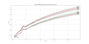
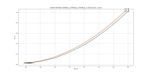
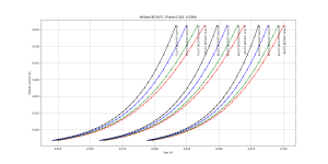
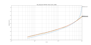
Next is FQP3N30 which is mislabeled on the graphs as FQP3N20.
This TO-220 MOSFET has much lower capacitance than IRFP240: 5x lower Ciss, 10x lower Coss, 20x lower Crss... while its transconductance is only a bit lower at low current, and about half that of IRFP240 at higher current. So it has a better product of gm*capacitance than IRFP240.

^ IRFP240 is on top of gm graph ; FQP3N30 on bottom. For next graph, IRFP is on the left (it has lower threshold) and FQP on the right.

Its Vbe tempco is higher than IRFP240 (in absolute value, about 2mV/°C more) but unlike FQP19N20 that's compensated by the lower transconductance, also it can't be used alone in a power amp since the current and dissipation ratings are too low. If several are used in parallel they can have a bit higher source resistor which also helps with bias stability. That looks good.
Surprisingly, its thermal capacity (and RthJC) is only about 2.5-3x worse than IRFP240... while its capacitance is better by a much larger factor. The low capacitance suggests a tiny chip and tiny thermal performance, but maybe it's just a more modern process.

So it looks like 2-3 of these FETs would be a good candidate to beat the old workhorse IRFP240... The AC tests will tell more.
This TO-220 MOSFET has much lower capacitance than IRFP240: 5x lower Ciss, 10x lower Coss, 20x lower Crss... while its transconductance is only a bit lower at low current, and about half that of IRFP240 at higher current. So it has a better product of gm*capacitance than IRFP240.
^ IRFP240 is on top of gm graph ; FQP3N30 on bottom. For next graph, IRFP is on the left (it has lower threshold) and FQP on the right.
Its Vbe tempco is higher than IRFP240 (in absolute value, about 2mV/°C more) but unlike FQP19N20 that's compensated by the lower transconductance, also it can't be used alone in a power amp since the current and dissipation ratings are too low. If several are used in parallel they can have a bit higher source resistor which also helps with bias stability. That looks good.
Surprisingly, its thermal capacity (and RthJC) is only about 2.5-3x worse than IRFP240... while its capacitance is better by a much larger factor. The low capacitance suggests a tiny chip and tiny thermal performance, but maybe it's just a more modern process.
So it looks like 2-3 of these FETs would be a good candidate to beat the old workhorse IRFP240... The AC tests will tell more.
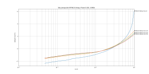
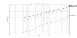
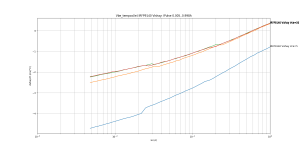
IRF610 (Vishay) vs FQP3N30 (ON), two similar FETs (on paper):
IRF610 has...
- similar capacitance
- lower transconductance (especially at low current)
- lower Vbe tempco
- worse thermal performance
IRF610 has...
- similar capacitance
- lower transconductance (especially at low current)
- lower Vbe tempco
- worse thermal performance
Attachments
Thanks ")
This scriptable setup is damn convenient, I solder the transistor in, press ENTER, and it does everything. So, here are four samples of FQP3N30 from the same tube:
gm vs current and threshold voltage tempco: perfect match, no need to post curves...
Vgs @ 25mA, Vds=25V, Tj=50°C:
4.586V
4.6V
4.62V
4.632V
Current @ Vgs= 4.63V,
32 mA
29.8 mA
25.0 mA
23.7 mA
Vgs @ 1A
5.938
5.953
5.982
5.985
Current @ Vgs=5.95V
0.95A
0.96A
0.99A
1.01A
I'd say pretty good current sharing and matching out of the box (the low transconductance helps). Although of course one (not me) would need to measure a few hundreds to get a proper statistical distribution.
Useful info: because the transconductance and tempco of all these FETs matches so perfectly, the offset between their Vgs doesn't depend on current or temperature, which means if you bother to match them they'll stay matched. And they can be measured with a multimeter, at a low current that doesn't heat them. It is impossible to measure Vgs at 1A with a multimeter, since self-heating will make it drift a lot more than the dispersion between FETs in this tube.
Attachments
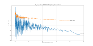
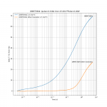
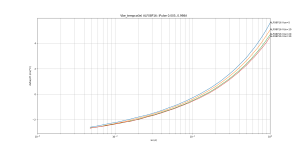
Well well, there's been a screwup: the Y axis on the transient thermal impedance measurements posted above should read "arbitrary units", due to the code using the wrong value of gain for the corresponding ADC. The comparisons made are still valid, no problem about that, but absolute temperatures and mV are wrong. This bug does not hit the other pulsed measurement graphs, which used the correct ADC gain constants.
Here's a corrected version.

I've used the Vgs tempcos at the current actually used in the transient thermal impedance test to get the actual temperature. I don't like doing this because it adds uncertainty, but I was too lazy to add the circuitry required to use the body diode as a thermometer, which is what serious people actually do. It looks weird at first that the three TO-220 devices have such different responses, but this matches the RthJC mentioned in the datasheets, which are quite different for the three devices.
I guess the difference between IRFP240 and MJL3281 is due to package. TO-247 is big, but the MJL3281 comes in TO-264, which is just huge, chunky, and heavy.
Anyway. The reason I did this transient thermal impedance test was to check the time constants between the device, the thermal interface material and the heatsink, and to get a feel how that would influence bias stability. And since the time constant is on the order of 0.1 second, that warrants some investigations on bias stability on this time scale, because that may correspond to some subjective sonic qualities, who knows.
Here's a corrected version.
I've used the Vgs tempcos at the current actually used in the transient thermal impedance test to get the actual temperature. I don't like doing this because it adds uncertainty, but I was too lazy to add the circuitry required to use the body diode as a thermometer, which is what serious people actually do. It looks weird at first that the three TO-220 devices have such different responses, but this matches the RthJC mentioned in the datasheets, which are quite different for the three devices.
I guess the difference between IRFP240 and MJL3281 is due to package. TO-247 is big, but the MJL3281 comes in TO-264, which is just huge, chunky, and heavy.
Anyway. The reason I did this transient thermal impedance test was to check the time constants between the device, the thermal interface material and the heatsink, and to get a feel how that would influence bias stability. And since the time constant is on the order of 0.1 second, that warrants some investigations on bias stability on this time scale, because that may correspond to some subjective sonic qualities, who knows.
I've also measured D44H11, a BJT that would make a nice driver. It's like a cheaper lower voltage MJE15030, fast, nice SOA, flat hFe... and while I'm sure I have some MJE15030 somewhere, I couldn't find them. I'll order some. So here we go.
It actually has higher gm than MJL3281, which I put on the graphs for comparison.
It actually has higher gm than MJL3281, which I put on the graphs for comparison.
Attachments
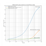
Can this method show Spirito thermal instability?
Hypothesis: two tests at the same power, but different Vds, could give different Vgs transient if the FET is getting hotspots.
Result for FQP3N30: exactly the same Vgs transient (once normalized for the different tempco at different currents). But that's FQP3N30, which is supposed to be nice in linear mode.

So I try AO4840, a small dual NMOS in SO-8 package, and aim for the edge of the SOA.

Result for AO4840: no noticeable difference between the two Vds/Id combinations.

But its datasheet SOA does not exhibit Spirito instability, so that's not a very strong confirmation the hypothesis is wrong. Unless the datasheet is optimistic, which is likely. Since I don't have any other good FET candidate that is known to pop when used in linear mode, I'll just leave it there.
Hypothesis: two tests at the same power, but different Vds, could give different Vgs transient if the FET is getting hotspots.
Result for FQP3N30: exactly the same Vgs transient (once normalized for the different tempco at different currents). But that's FQP3N30, which is supposed to be nice in linear mode.
So I try AO4840, a small dual NMOS in SO-8 package, and aim for the edge of the SOA.
Result for AO4840: no noticeable difference between the two Vds/Id combinations.
But its datasheet SOA does not exhibit Spirito instability, so that's not a very strong confirmation the hypothesis is wrong. Unless the datasheet is optimistic, which is likely. Since I don't have any other good FET candidate that is known to pop when used in linear mode, I'll just leave it there.
Last edited:
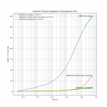
Alright, another screwup: all the X-axis on the thermal transient measurement graphs are also wrong
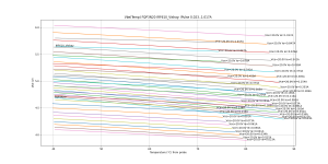
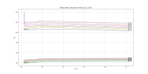
Still no problem for comparisons. I've fixed it and therefore we can have a "who has the biggest chip" contest among small signal transistors.

So, for example, say we have an amplifier with a LTP input stage having two BC547C, biased at 30V 1.5mA each. So they dissipate 45mW each. During clipping, one of the input transistors is off and the other gets all the current, so that's a difference in dissipated power of 90mW. If clipping lasts for 1ms, that's 90 µJoule, so what will the resulting offset be?
Looking at the graph, 0.6W over 1ms (600µJ) results in 17°C, and since the effect is linear, 90µJ would result in a 2.5°C temperature difference after this millisecond of clipping, or 5-6mV offset voltage.
Is this enough to upset the balance of the input stage until temperature equalizes? Probably not... but it would be interesting to measure the distortion right after clipping...
On the graph above, the winners are the low noise transistors, especially 2SC3324 from Toshiba (which is unfortunately EOL), and in thru-hole, 2N5551 and KSC1845.
The two HF transistors (MMBTH10/MMB T5179) seem to have the highest thermal impedance, which makes sense.
BC547C and BC849C seem to have similar chips (the action below 1ms is the same) and of course different leadframes so they diverge after 1ms. That makes perfect sense.
BC547C and BC550C are quite different, these are old transistors without labels, so the manufacturers are probably different.
Interestingly, the tiny SOT23 MMBT3904 from ON has much lower thermal impedance below 1ms than the thru-hole 2N3904 from Fairchild. Did the latter get a die shrink?
Some slightly larger transistors now.

2SCR293 is a very nice SOT-89 low voltage medium current transistor. It has very high hFe and high fT too.
KSC3503 is a favorite for cascodes. I've included it because a cascode gets a lot of variation in dissipated power, so its temperature will move around, so its hFe will change, which means it will inject a temperature-dependent offset current into the circuit. If it is a folded cascode, the input stage will have to compensate for it without any gain provided by a VAS transistor. So it makes sense to use a cascode on the VAS with low transient thermal impedance. KSC3503 delivers much better numbers than the TO-92 transistors.
If the transistor is used as VAS instead of cascode, then open loop gain depends on its hFe, so that applies too.
I did not do the complete characterization for all these transistors, so I don't have hFe vs temperature. I'll do it later.
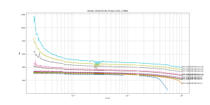
I've redone the power transistors, with correct X axis.

The chunkiness of MJL3281 is impressive...
Still no problem for comparisons. I've fixed it and therefore we can have a "who has the biggest chip" contest among small signal transistors.
So, for example, say we have an amplifier with a LTP input stage having two BC547C, biased at 30V 1.5mA each. So they dissipate 45mW each. During clipping, one of the input transistors is off and the other gets all the current, so that's a difference in dissipated power of 90mW. If clipping lasts for 1ms, that's 90 µJoule, so what will the resulting offset be?
Looking at the graph, 0.6W over 1ms (600µJ) results in 17°C, and since the effect is linear, 90µJ would result in a 2.5°C temperature difference after this millisecond of clipping, or 5-6mV offset voltage.
Is this enough to upset the balance of the input stage until temperature equalizes? Probably not... but it would be interesting to measure the distortion right after clipping...
On the graph above, the winners are the low noise transistors, especially 2SC3324 from Toshiba (which is unfortunately EOL), and in thru-hole, 2N5551 and KSC1845.
The two HF transistors (MMBTH10/MMB T5179) seem to have the highest thermal impedance, which makes sense.
BC547C and BC849C seem to have similar chips (the action below 1ms is the same) and of course different leadframes so they diverge after 1ms. That makes perfect sense.
BC547C and BC550C are quite different, these are old transistors without labels, so the manufacturers are probably different.
Interestingly, the tiny SOT23 MMBT3904 from ON has much lower thermal impedance below 1ms than the thru-hole 2N3904 from Fairchild. Did the latter get a die shrink?
Some slightly larger transistors now.
2SCR293 is a very nice SOT-89 low voltage medium current transistor. It has very high hFe and high fT too.
KSC3503 is a favorite for cascodes. I've included it because a cascode gets a lot of variation in dissipated power, so its temperature will move around, so its hFe will change, which means it will inject a temperature-dependent offset current into the circuit. If it is a folded cascode, the input stage will have to compensate for it without any gain provided by a VAS transistor. So it makes sense to use a cascode on the VAS with low transient thermal impedance. KSC3503 delivers much better numbers than the TO-92 transistors.
If the transistor is used as VAS instead of cascode, then open loop gain depends on its hFe, so that applies too.
I did not do the complete characterization for all these transistors, so I don't have hFe vs temperature. I'll do it later.
I've redone the power transistors, with correct X axis.
The chunkiness of MJL3281 is impressive...
Thanks for this wealth of interesting and useful information.
I look forward to your next tests, and the lessons you will ultimately draw, if you care to share them with the community.
This will help tackling the elusive "memory distortion", something that has not been addressed in a completely satisfactory and systematic manner so far
I look forward to your next tests, and the lessons you will ultimately draw, if you care to share them with the community.
This will help tackling the elusive "memory distortion", something that has not been addressed in a completely satisfactory and systematic manner so far
I've polished the code and the hardware a bit...
It is pretty slow because I'm using a pair of bench power supplies to step voltages, and these can't do more than 10 updates/second. It is tempting to build a board just for this, with an actual fast DAC... Maybe later.
Now, one of these transistors really starts suffocating at low Vce...
It is pretty slow because I'm using a pair of bench power supplies to step voltages, and these can't do more than 10 updates/second. It is tempting to build a board just for this, with an actual fast DAC... Maybe later.
Now, one of these transistors really starts suffocating at low Vce...
Attachments
I've tried matched transistor pairs: PMP4201 DMMT3904 DMMT5551... and I forgot to order the BCM849, so that will wait.
The dual transistor package means the influence of ambient (board temperature, airflow...) should be the same on both transistors, so this is nice. But will it keep the two transistors at the same temperature if one dissipates more power?
By heating one transistor in the matched pair and tracking the other's Vbe, the thermal time constant can be estimated. It's pretty slow, several seconds, and the second transistor doesn't catch up. So, thermal tracking is pretty much non-existent, which is logical since these are two independent chips in epoxy. It's not a monolithic matched pair.
Attachments
Probably not, TIP41 fT is too slow at 3MHz...
Speaking of which,
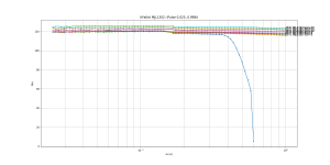
Left: MJL1302 works very well at low Vce, to squeeze the juice out of these last volts... and hFe is really stable and constant.
Right: 2SA2039 would make an excellent driver for a BJT output stage, or output stage for a headphone amp. It's fast (>300MHz fT), high current, high flat hFe up to 1 Amp, cheap... It's low voltage and low-ish power though, so to use it as driver, it would need to be bootstrapped, but that's not a problem.
Speaking of which,
Left: MJL1302 works very well at low Vce, to squeeze the juice out of these last volts... and hFe is really stable and constant.
Right: 2SA2039 would make an excellent driver for a BJT output stage, or output stage for a headphone amp. It's fast (>300MHz fT), high current, high flat hFe up to 1 Amp, cheap... It's low voltage and low-ish power though, so to use it as driver, it would need to be bootstrapped, but that's not a problem.
Attachments
I've wired the P-channel setup.
But wtf?
The three IRF PMOS FETs (and the lateral, of course) have a zero Vgs tempco point at a much lower current than what the datasheet says. That's quite user-friendly. Once again the urban legend of FETs having thermal runaway bites the dust. That could perhaps even mean they are safe from Spirito instability, but this measurement won't show that.
Attachments
- Home
- Amplifiers
- Solid State
- Assorted Pulsed transistor measurements