john_ellis said:Here's what I would have thought of initially.
Not optimised, but works at 200kHz.
Wow, thank you so much! I'll give that a try.
Also, I realized I uploaded the wrong image for post #18. Was trying to do something more like this with a voltage divider on the positive feedback. Thinking this might work off the emitter resistor so I'm not dealing with 100s of volts.

OldDIY said:Install a jumper instead of C3. Exclude C4. Calculate the resistor values for the modified voltage.
Thank you for all of these example circuits! I have been saving them and simulated a few as originals (they do work very well), but my attempts at modifying them with higher voltage BJTs doesn't work as well as one would hope. Will have to play with them more as time allows... hoping I can get an iteration of the original circuit to work. I think we're getting closer...
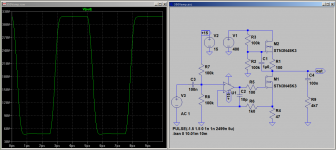
Here's what I would have thought of initially.
Not optimised, but works at 200kHz.
I just ran this circuit in simulation, it just plain works!

Going to play with it some more, but so far amazing!
Good luck with that, 400 is about all I’ve ever seen. If you want something “bigger” than MJE5731A, there’s the MJE5852. Smaller, there is the KSA1156. But 400 volts is all you’re going to get. These types seem to work fine (within the pretty poor SOA limits) on +/-165 volt supplies.
Circuit in #21: U2's inverting input has no DC bias current, so its broken in reality whatever the simulator claims!
Correct--my attempts at driving Q4 with the opamp were failed at the time of my post. Now have it resolved--using the -15v bias & feedback from Vout to set the opamp correctly. Works much better, indeed, but not perfect. Still have a bit of a non-linear sine wave at the output at higher frequencies with rail-to-rail output. Still tweaking.
When I said it works great in simulation I was referring to John Ellis' push-pull design. Getting really clean output sine wave at 100kHz. Will do more thorough simulations on both in the next few days.
Recommend MJE5731, or 5731A, not 5730. Spec for '31 is 350V. Spec for '30 is only 300V.
Yes--using MJE5731A for my actual transistors (5730 is only for LTspice model). Early on in this project, I had mistakenly ordered 5730 and found out very quickly that did not work at voltages >350!
Will post back when I've had time to run some more simulations
100kHz sine wave with original Class A amp:

Corrected opamp drive of Q4:

brief explanation: The hi-side power-MOSFET acts as artificial inductor and auto-biases the output to half supply voltage, independent of class A-bias current setup by the low-side power-MOSFET.
The low-side is a voltage driven current source with an admittance of 1/R4=1/47R=21mA/V.
Voltage gain is R9/R4=4k7/47R=100V/V
There is no overall feedback.
The op-amp in this simulation has Ft=10MHz and SLR=10V/us.
Being a class A-amp appropriate heatsinks are mandatory.
The low-side is a voltage driven current source with an admittance of 1/R4=1/47R=21mA/V.
Voltage gain is R9/R4=4k7/47R=100V/V
There is no overall feedback.
The op-amp in this simulation has Ft=10MHz and SLR=10V/us.
Being a class A-amp appropriate heatsinks are mandatory.
Last edited:
bucks bunny said:I just drew a quick and dirty simulation with power-MOSFETs in class-A. Showing 200kHz squarewave output. Could be useful as a starting point
Thank you so much! That looks like a good alternative to get even more out of this amp design.
We've actually improved on the output response at 100kHz since my last post... now 100k looks great, able to push toward 200k before things get non-linear. I'm going to build this BJT design with Q4 driven by the opamp first, since I have most of the circuit already built. Then once I have a functioning amp I can go back and try building some alternate designs and see if I can improve on output and/or efficiency.
Yes on the heatsinks
This is the current test bed--we may even go with forced cooling in application.
- Home
- Amplifiers
- Solid State
- Class A amp design--need help with slew rate, transistor selection