I'm working on my first amp design project with a friend (I've been involved in tube and solid state audio amp repair for many years), this isn't exactly for audio reproduction, but I know there's tons of overlap with what we're trying to do and the amps here. Please let me know if this is inappropriate for this forum or section.
Long story short, we are trying to achieve 10-100kHz bandwidth, but high voltage/low current output. +/-175v pk, 40mA into a 4.7k ohm load.
We've gone through a few different design iterations, but are now kind of stuck with a poor slew rate (this is my fault for not understanding the LTspice AC simulation did not give us a picture of what was happening with large signals.) The signal starts getting horribly non-linear on the positive going peaks past 30kHz when driven rail-to-rail. Can
Started out with Class AB, couldn't get the bandwidth past ~20kHz. Changed to Class A with a diff pair input, but that had bias stability issues. Revised to using an opamp as the voltage amp--simulation shows amazing bandwidth past 1Mhz, but could not get past 30-40kHz at full scale output. Discovered that the slew rate needs to be 70V/us to achieve this at 100kHz, we only have 20-30V/us.
Using an MJE5731 and TIP50 as the output transistors (had to parallel the MJEs to keep in the SOA). Perhaps there's simply a better transistor to use?
Or is there a different design topology we should consider entirely? I've tried a few other circuits in Spice with MOSFETs and none can really achieve what we're looking for. Am I correct that these high voltage/high power transistors are simply not going to achieve the speed we need?
Open to any suggestions or feedback!
Thanks,
Michael
Started out with Class AB, couldn't get the bandwidth past ~20kHz. Changed to Class A with a diff pair input, but that had bias stability issues. Revised to using an opamp as the voltage amp--simulation shows amazing bandwidth past 1Mhz, but could not get past 30-40kHz at full scale output. Discovered that the slew rate needs to be 70V/us to achieve this at 100kHz, we only have 20-30V/us.
Using an MJE5731 and TIP50 as the output transistors (had to parallel the MJEs to keep in the SOA). Perhaps there's simply a better transistor to use?
Your slew rate is limited by the large nonlinear Miller capacitances of the TIP50 and 5731. Try darlingtoning them with something like KSA44/94 to boot strap that effective input capacitance. I use that very combination as a VAS in my highest power PA amps, which operate at similar voltages. Then I actually end up adding a small linear Miller capacitor. Cascode is another option. And rather than paralleling the VAS, you may be better off using parallel emitter followers after. Two pair of TIP50/MJE5731, biased class AB at 10 mA each. That should give you 40 mA peak output current while still in class A without the SOA problems. If you do add the followers, you probably need to add lead compensation to the overall feedback loop. I always do - never seems to be stable without it regardless of what simulations say. You won’t get any 1 MHz small signal bandwidth, but a couple hundred kHz easy.
Last edited:
Wow, thank you all for the replies! Lots of excellent ideas! More than I could have hoped for 
I will try simulating the circuit with a these variations--changing to a 350v/grounded supply configuration may be easiest given what's already built. But adding a Darlington or changing to a BU508 might work just as well. I'll play with these and post back...
Had never crossed my mind to bridge two amps either--that may help in a future rev as well if the application demands further increases in output voltage.
wg_ski, I found a KSA940TU from ON Semi, but having trouble locating KSA44. Is that the correct transistor number? These are low voltage transistors, though?
I will try simulating the circuit with a these variations--changing to a 350v/grounded supply configuration may be easiest given what's already built. But adding a Darlington or changing to a BU508 might work just as well. I'll play with these and post back...
Had never crossed my mind to bridge two amps either--that may help in a future rev as well if the application demands further increases in output voltage.
Try darlingtoning them with something like KSA44/94
wg_ski, I found a KSA940TU from ON Semi, but having trouble locating KSA44. Is that the correct transistor number? These are low voltage transistors, though?
...poor slew rate....horribly non-linear on the positive going peaks past 30kHz...
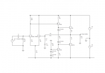
As bucks bunny says, Q4 base current is the bottleneck. What I see is that the 47k 0.02mA pull-down is much too weak. For great drive you want the standing current past the base to be => Ib. Change R14 to 1K to get more standing current.
R1= zero seems wrong. You have a ton of gain in Q4; adding gain in Q2 seems reckless. Make R1 = R14 for unity gain.
Q1 does nothing. It takes 9V off of Q2 stress, whoopeedoo. The 10K base divider may be another bottleneck; I'm not going to figure that, just take Q2 out.
Attachments
Last edited:
You have an output stage which uses a constant current pull-up (2xMJE5730) with an active output device (TIP50). The output current will be limited to the pull-up current (18mA as PRR showed).
If it were me, I would use a push-pull output stage so that the peak current can be doubled.
That would mean installing a driver transistor stage, probably cascoded even if a Miller capacitor is added, and the output with the TIP50 uppermost and an MJE5730 underneath as "emitter followers", and either a constant current drive to the driver transistor or simply a bootstrap capacitor.
The input would need to be rearranged a little to accommodate the changes.
You have an output stage which uses a constant current pull-up (2xMJE5730) with an active output device (TIP50). The output current will be limited to the pull-up current (18mA as PRR showed).
If it were me, I would use a push-pull output stage so that the peak current can be doubled.
That would mean installing a driver transistor stage, probably cascoded even if a Miller capacitor is added, and the output with the TIP50 uppermost and an MJE5730 underneath as "emitter followers", and either a constant current drive to the driver transistor or simply a bootstrap capacitor.
The input would need to be rearranged a little to accommodate the changes.
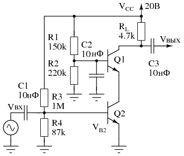
This is the design we started out with, but couldn't get a bandwidth past 20kHz:

Post 1:This is the design we started out with, but couldn't get a bandwidth past 20kHz:
It looks like the Q5 is problem there, as it attenuates signal from Q1 collector.
Post 15:
Signal is attenuated through R2 (R3) and R1 (R4) divider.
Design have flows, you should take the proved ones like given by other members here and learn how it works. Possibly think of improvements, but later...
Sorry I didn't mention that Q5 isn't actually wired in my breadboard amp--that was designed in as a safety to pull away base current from Q4 as a limiting device, but for diagnostics I left it out.
I've been tinkering with this design as it seems to be the most straightforward way to take what I have existing and get something working. Having a bit of trouble getting this to work. Please excuse my inexperience with the design sides of things!
I've googled and found a few examples of opamps driving an NPN, but I'm still getting stuck. I know I need Q4 Ib=112 uA to get Ic=57mA and balance the output at 175vdc. How do i set this up to provide the correct feedback to the opamp? Do I still need the integrating cap?
Do you have a schematic of this you wouldn't mind sharing? I'd be very interested to see other implementations that work.
bucks bunny said:With R3=22k the base current of lowside npn is limited to about 8mApp. Not very much for fast switching and this is the bottleneck for your slew rate. I would suggest a single supply 350V and the op-amp directly driving the npn base.
I've been tinkering with this design as it seems to be the most straightforward way to take what I have existing and get something working. Having a bit of trouble getting this to work. Please excuse my inexperience with the design sides of things!
I've googled and found a few examples of opamps driving an NPN, but I'm still getting stuck. I know I need Q4 Ib=112 uA to get Ic=57mA and balance the output at 175vdc. How do i set this up to provide the correct feedback to the opamp? Do I still need the integrating cap?
An externally hosted image should be here but it was not working when we last tested it.
wg_ski said:Try darlingtoning them with something like KSA44/94 to boot strap that effective input capacitance. I use that very combination as a VAS in my highest power PA amps, which operate at similar voltages.
Do you have a schematic of this you wouldn't mind sharing? I'd be very interested to see other implementations that work.
- Home
- Amplifiers
- Solid State
- Class A amp design--need help with slew rate, transistor selection