Thanks a million for all. I don't have an oscilloscope but I have the C531 on order, should be here next week. I've ordered several as the C 533 is the same with a lower voltage. 47uF 63V and 50V caps. I have those very small value other e caps there but as you are suggesting I'll change the C531 first and see what happens. I don't have any 22-100 uF caps unfortunately.
One question. Why is that muting required? I did notice that when I switch the amp on there is a 5 second pause before the sound comes on. Never quite understood that but then again I am not very knowledgeable on this.
Thanks again for all the help
One question. Why is that muting required? I did notice that when I switch the amp on there is a 5 second pause before the sound comes on. Never quite understood that but then again I am not very knowledgeable on this.
Thanks again for all the help
'Snap' - mine look basically the same for those scenarios, albeit with different JFET & diode models etc.
I hadn't really considered C533, probably because I've had the C531 problem before. Good to see my sim is comparable anyway")
This is with C531 as 100uF, just for comparison - you can see when the JFETs open.

I hadn't really considered C533, probably because I've had the C531 problem before. Good to see my sim is comparable anyway
This is with C531 as 100uF, just for comparison - you can see when the JFETs open.
You can fit a higher voltage rating in place of a lower but not the other way around.
Muting is done to try and minimise any unpleasant noises an amp might make at power on and power off. These days it is normally done with proper relays that only connect the speakers after a few seconds have passed and that then disconnect quickly when the power is turned off.
Any circuit with capacitors in it takes a finite time to stabilise to the correct operating points as the capacitors have to charge up via the circuitry around them. In an audio stage that charging causes the output voltage of the amp to alter and you hear that as a noise or a thump or a bang.
An amp ideally should be absolutely silent when you turn it on and off but many are not.
Your muting circuit simply prevents anything from the preamp stages being passed to the power amplifier and so the inherent noises the power amp might make will still be heard.
'Snap' - mine look basically the same for those scenarios, albeit with different JFET & diode models etc.
It looks very similar
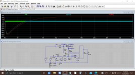
This is mine with audio going in from the start (green) and then the output from the FET (lighter blue) and the FET control voltage.
I seem to recall problems with the original sim and it not modelling the diode leakage well enough for the circuit to work as I see I have the diode linked out in the original sim. I don't think it pulled the gates negative from memory... however
Attachments
Mine differs in the exact values - but I had a 3020 power supply simulation already set up, so used that to power the +ve voltage to the JFET drive.
Red is the JFET drive voltage (junction of R547 & R548 in the 3020A)
Green is the audio signal at the JFET output
and for Peter - the Blue line is how the 3020 +ve supply voltage 'builds' after you turn the amp on... so you can see the initial ca. 10-20 seconds it takes to stabilise to it's final, running, value. The exact values may differ slightly, but the trend will be identical.

Mooly - the previous simulation you looked at was for a 3120, and specifically DC-offset voltage at the pre-out terminals. You suggested a modification to the circuit to reduce the pre-out offsets - which has been working perfectly in mine for the past year or so, it's in the earlier thread that was linked.
Red is the JFET drive voltage (junction of R547 & R548 in the 3020A)
Green is the audio signal at the JFET output
and for Peter - the Blue line is how the 3020 +ve supply voltage 'builds' after you turn the amp on... so you can see the initial ca. 10-20 seconds it takes to stabilise to it's final, running, value. The exact values may differ slightly, but the trend will be identical.
Mooly - the previous simulation you looked at was for a 3120, and specifically DC-offset voltage at the pre-out terminals. You suggested a modification to the circuit to reduce the pre-out offsets - which has been working perfectly in mine for the past year or so, it's in the earlier thread that was linked.
It is. Why not click my signature line to see how to get started. LTXVII is pretty similar.
If you install it I can give you some files that will just click and run (like the NAD). A few minutes and you can be up and running.
LTspice Simulator | Analog Devices
If you install it I can give you some files that will just click and run (like the NAD). A few minutes and you can be up and running.
LTspice Simulator | Analog Devices
Mooly - the previous simulation you looked at was for a 3120, and specifically DC-offset voltage at the pre-out terminals. You suggested a modification to the circuit to reduce the pre-out offsets - which has been working perfectly in mine for the past year or so, it's in the earlier thread that was linked.
Thanks
So that is why I added a diode clamp. It's like a zillion posts back in time for me Good to hear the mod worked OK

i will do that tomorrow.Im not sure i am ever going to be anywhere near what you guys do, but it would be good to be able to start doing this stuff as it would help me better understand things i think. Being a more practical person, i think i can progress better than just reading text only.It is. Why not click my signature line to see how to get started. LTXVII is pretty similar.
If you install it I can give you some files that will just click and run (like the NAD). A few minutes and you can be up and running.
LTspice Simulator | Analog Devices
I'm sure it would help you a lot. As well as running simulation like these we can also show typical DC voltages...
Anyway, try it and when you have installed it then I'll post you some circuits that will just click and run and you can have a probe around them and see what is going on.
Anyway, try it and when you have installed it then I'll post you some circuits that will just click and run and you can have a probe around them and see what is going on.
So back to the problem Nad, I have now changed the two caps, the C531 and the C533. Managed to get hold of a few. The caps are the same value, 47uF but higher voltage. Both of them and they are brand new. Still no sound. Sound comes back like before when the meter is connected to the diode. The other three little caps I have the values but the voltages are lower unfortunately so I have not changed them
Peter
Peter
OK, not what I'd expected, but that's life... Before anything else, I'd suggest to repeat the measurements now, with the new caps in place:
1. Voltage DC between the red switch wire and ground with the amp on.
2. Voltage DC between the white switch wire and ground with the amp on.
3. The voltage DC at each end of R547, R548, and R549 (6 measurements) and at each end of D507 (2 measurements), and at each end of D505 (2 measurements).
4. Would maybe also be useful if you could note the colour bands on R547 and R548 (not critical but they changed values somewhat in some amps).
In each case, the black meter lead goes to the metal chassis of the amp (ground), and the red lead to the point being measured. Note whether the measurements are +ve or -ve in each case.
Seems like a lot, but it's 5 minutes work, and should give a complete picture of the muting circuit now.
Hmmm. Not what I would have expected either... but fault finding is all about gathering evidence and that is all part of the fun of the chase.
In post #34 you measured this:
Can you just confirm that you did check and measure the 68k. You must isolate one end of the resistor to get an accurate reading. Alternatively, if you have any 47k to 100k resistors then you could tag one across the 68k as a quick test and see if it works while leaving the original in place.
If all that is OK then I think you have to disconnect the white wire from the board and see if the circuit unmutes. If it works then the switch is leaky internally.
If it it still does not work with the wire disconnected then remove C531 leaving the white wire still disconnected.
It must now work at this point as there is nothing else left beyond really weird things like the board itself being conductive... which we can test
And if by chance it still does not work at this stage then we are most likely looking at a problem around the other two caps and diodes.
In post #34 you measured this:
Red wire 56V negative
White wire 20-21V also negative. Doesn't stay steady
Can you just confirm that you did check and measure the 68k. You must isolate one end of the resistor to get an accurate reading. Alternatively, if you have any 47k to 100k resistors then you could tag one across the 68k as a quick test and see if it works while leaving the original in place.
If all that is OK then I think you have to disconnect the white wire from the board and see if the circuit unmutes. If it works then the switch is leaky internally.
If it it still does not work with the wire disconnected then remove C531 leaving the white wire still disconnected.
It must now work at this point as there is nothing else left beyond really weird things like the board itself being conductive... which we can test
And if by chance it still does not work at this stage then we are most likely looking at a problem around the other two caps and diodes.
Attachments
Excuse me but which one is the 68K? Is that the R547? If yes I've posted the new measurements. I have a whole bunch of resistors here but I have not printed up the color codes. If you tell me what color code I should be looking for I'd probably find one. If it's the R547 I can check if I have any gold green and red code resistors. also when you say I have to isolate the resistor you mean I have to lift one of the legs?
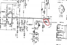
On the diagrams I posted above it looks like R548 and that is marked as 68k. R547 is the 150k. There seem to be different variations of the circuit floating around.
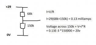
Look at the circuit in the earlier post and my drawing here. We have a 68k and a 150k in series and these two are across the +29v supply. Try and follow the calculation
This gives us a +20v bias supply to turn the FET on. The cap, the switch and anything D507 connects to should not be able to alter this voltage.
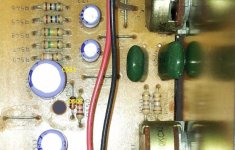
The photo Goldie posted clearly shows two 150k resistors. Brown, Green and Yellow Different to the diagram I posted but anything in that range will work as a test. Two 150k's as in the picture would give an equal voltage split and give about 15v bias voltage rather than 20.
Either unsolder one end of each to test the value on your meter or do the following:
Simple test. Get a new resistor of around 100k to 220k and just bend the legs and carefully dab it across R547.
Does the sound come back???
If no then repeat for R548 on the basis the diagrams may be different.
If still no sound then proceed with isolating the white wire and cap as I suggested earlier.
(Use your meter to confirm the value of any new resistor you try if you are unsure of colour codes.)
Look at the circuit in the earlier post and my drawing here. We have a 68k and a 150k in series and these two are across the +29v supply. Try and follow the calculation
This gives us a +20v bias supply to turn the FET on. The cap, the switch and anything D507 connects to should not be able to alter this voltage.
The photo Goldie posted clearly shows two 150k resistors. Brown, Green and Yellow Different to the diagram I posted but anything in that range will work as a test. Two 150k's as in the picture would give an equal voltage split and give about 15v bias voltage rather than 20.
Either unsolder one end of each to test the value on your meter or do the following:
Simple test. Get a new resistor of around 100k to 220k and just bend the legs and carefully dab it across R547.
Does the sound come back???
If no then repeat for R548 on the basis the diagrams may be different.
If still no sound then proceed with isolating the white wire and cap as I suggested earlier.
(Use your meter to confirm the value of any new resistor you try if you are unsure of colour codes.)
Attachments
I can check if I have any gold green and red code resistors. also when you say I have to isolate the resistor you mean I have to lift one of the legs?
Gold is the tolerance band and is 5%. That doesn't matter here.
In Goldies picture we have Brown (1), then Green (5) and then Yellow (4) which gives 150,000 ohms.
R549 in that picture is the 390 ohm to the switch. The is Orange (3), White (9) and Brown (1) and so we have 390
Those third bands, the Yellow and Brown are multipliers, the number of zeros we add to the first two numbers.
So we get 15 and four zeros and 39 and one zero.
The resistors above those are the 10 megohm to the FET's. We have Brown (1), Black (0) and then Blue (6) which is 1, then 0 followed by 6 zeros giving 10,000000 or ten million ohms.
Modern resistors switched to four and five band codes which will confuse you if you are not aware and so check any in your bag of spares with a meter first.
You are so near to fixing this
(we have to isolate by lifting one end of a resistor to measure it because of interaction with other parts around it. If we don't do that we get inaccurate results, particularly for higher value parts)
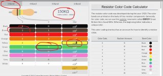
Try this resistor calculator:
Resistor Color Code Calculator (3-band, 4-band, 5-band and 6-band) - Codrey Electronics
Make sure you select 'Three Band' at the top and then click out the colours.
Attachments
Red wire 56V negative
White wire 20-21V also negative. Doesn't stay steady
The only way I've found to give anything like -20V on the white wire, if that's what it still is, is to add ca. 200k leakage resistance in the switch itself.
That wouldn't necessarily be a major problem if so, as there's a completely unused set of spare contacts available on the switch - but it's better to confirm by measurement first.
The R547 and 548 are green and red in my machine besides gold which you say doesn't matter. When I touch either of them with one of the following resistors the sound comes on. I just dabbed the resistors as you suggested and I have not removed them.
78 ohm I have several of this. Color is white red and black. From outside in.
46 k ohm
98 k ohm
All of these brought the sound back. The meter was set on SCAN in the ohm range. It's kind of automatic and whistles if something is not right. I have another meter which the Nakamichi people call VTVM. Analog and I have never quite learned how to use it. Finally one more digital meter which has a 20 k ohm setting but it needs battery. So should I remove either or both the
R547 or 548?
- Home
- Amplifiers
- Solid State
- Nad 3020A developed problems