Is it Q156? (If so, Is C164, C160 ok?)I desoldered Q154 he is ok,but without Q154 R245 no blown,no hot.
No,Q156 ok,c160,c164 okIs it Q156? (If so, Is C164, C160 ok?)
Last edited:
The last news.
I resoldered Q154 and desoldered one pin of RT101.
Amplifier power on,R245 33 ohm no blown,not hot.
After resoldered Q154 /RT101, is power amp. running?
Interesting. Is front panel working (led lights)? I wanted to ask power led colour.
is D118,D120 ok? I think, test all diods on c352.
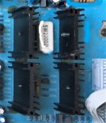
I came across a web, one of the photo showed the C352 mainboard,
there is a 200 ohm 5w resistor in the middle of the 4 heatsinks,
you can check if that is the R245,
*****
suggest you post a detail photo of the inside,
so members can know more about the amp.
*****
you mentioned about P102B, pin1 +50v, pin2 -40.5v,
unplug it and measure it if the voltage will go back to +50v and -50v.
you must solve this imbalance voltage first.
if imbalance persist, go to page 4, Power Supply.
check all the components,
SCR, transistors, resisters, capacitors...bad joints
also
measure P101B,,
the two AC connections , ac voltage to ground,
******
check R251 voltage,
12v became 26v out means Q159, Q160 could be defective, may be coursed by shortage somewhere, if found defective take it out first, replace only until you found the fault
and fix.
*****
for the + -18v, do your best to find any short along the rail.
the circuit, make sure you fix everything ok .
I understand. We couldn't know panel side is faulty or not..
Disconnection of Q154 stops power amplifier. Is this right?
No, without Q154 Amplifier power on and R245 no blown
I came across a web, one of the photo showed the C352 mainboard,
there is a 200 ohm 5w resistor in the middle of the 4 heatsinks,
you can check if that is the R245,
*****
suggest you post a detail photo of the inside,
so members can know more about the amp.
*****
you mentioned about P102B, pin1 +50v, pin2 -40.5v,
unplug it and measure it if the voltage will go back to +50v and -50v.
you must solve this imbalance voltage first.
if imbalance persist, go to page 4, Power Supply.
check all the components,
SCR, transistors, resisters, capacitors...bad joints
also
measure P101B,,
the two AC connections , ac voltage to ground,
******
check R251 voltage,
12v became 26v out means Q159, Q160 could be defective, may be coursed by shortage somewhere, if found defective take it out first, replace only until you found the fault
and fix.
*****
for the + -18v, do your best to find any short along the rail.
the circuit, make sure you fix everything ok .
R245 is 33 ohm 0.5w resistor
down load the C-320 schematic,
I found it looks the same with C-352,
the schematic is very clear without broken line , the link
NAD C 320BEE SERVICE MANUAL Pdf Download | ManualsLib
******
I found it looks the same with C-352,
the schematic is very clear without broken line , the link
NAD C 320BEE SERVICE MANUAL Pdf Download | ManualsLib
******
Q154 and the two op amps from the Impedance Sensing Circuit (ISC) which I am searching how it works. here's a link about ISC:
How to adjust NAD ISC circuit?
How to adjust NAD C370 ISC circuit?
How to adjust NAD ISC circuit?
How to adjust NAD C370 ISC circuit?
Thanks for the C320 PDF, Alexchoi,
So refreshing to have a schematic that isn't riddled with omissions -- and they didn't run out of little black 'connected' dots!
Looks like we'll need to agree / to stick with / or cast aside / C352 component designations, though. The very section we spent most of our time on -- the ±18V regulators -- has both 2 digit, and 4xx-series numbers. The C352 schematic is all 100's for Q's and C's, 200's for resistors.
Looks like any of the circuits that hold down Trig, like Q154 (C352) or Q421 (C320) have the job of keeping the power supply SCR's off, lowering voltage and/or current capability.
Cheers
I just learned how to insert link,
here's the photo link, it is one of the three images.
But again the link can't be shown here,
***********
I've edit the photo but don't know how to post it here.
***********
suggest to use a 5w 200r to replace R245 temporarily to locate the faults,
change it back to 33r 0.5w when everything fixed.
have you measure the ac voltages,
hope you fix it soon.
Last edited:
- Home
- Amplifiers
- Solid State
- NAD C352 Protect mode