Bipolar (bjt) transistors and MOSFET's are very different in operation. A major difference is that the bjt is essentially current driven meaning you inject a current into the base/emitter junction to turn it on. That can be pretty high in high current output stages, in other words the driver stage has to supply lots of current.
The mosfet is voltage driven and the gate draws virtually no current at all at DC and low frequencies. At high frequencies a bit of current is needed to charge and discharge the gate capacitance. In fact at DC the gate can literally acquire enough charge to turn the mosfet on simply by it 'floating' and not being connected to anything at all. The impedance of the gate is very very high indeed. The voltage needed to turn the FET on is quite high compared to a bjt (around 4v vs around 0.6)
I like using fets and the fact they draw little gate current makes driver stage design easier imo.
Lateral FET's are another one to look at and those are my favourite devices. These have a very low turn on voltage beginning at just 150mv or so.
I also use Fets & Mosfets and follow JLH,s design philosophy but you will find this subject generates a great deal of energy expended arguing the case between the two types of active devices.
It certainly did on EW --lasted for years ---and years with on one side JLH & several other designers including a well know Italian designer and the "opposition " which had at its head --who else but D.Self who if he is reading this must agree he was --well ferocious in his discrediting and technical permanent attack on all things Fet in relation to audio power amps.
This caused a big split in the UK with neither side willing to give ground ,I doubt even several decades later anything has changed but as I said before magazine sales of EW went through the roof and the letter pages were crammed with letters .
I got the feeling D.self enjoyed this ( correct me if I am wrong ) and there is no denying he is a very intelligent man and designer so give him his due but diplomacy was/is entirely missing from his personality .
He has made his name now worldwide and you must give him credit for that but that doesn't or didn't change my point of view of preferring JLH.
Transistors (bjts and fets) dont produce sound, the circuit there in does.
yes i am aware of this, but in terms of over all sound quality within the amplifier i was refering to realy
This is an excellent read ons this subject:
Bob Cordell Interview: BJT vs. MOSFET
Bob Cordell Interview: BJT vs. MOSFET
Ive heard that mosfets produce a better sound in amps is this true?
You've heard one of two diametrically opposed opinions on the subject. It is fair to say mosfets do sound different.
I am still to hear a mosfet amp matching the bass of a good Krell.
Ive heard that mosfets produce a better sound in amps is this true? do they work on the same principle?
It's more like IPS vs. IPS ,the OPS is just the magnifier.
OS
Ive heard that mosfets produce a better sound in amps is this true?
"I've heard" that lamb is better in meatloaf. This is not true for me.
...do they work on the same principle?
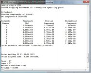
All audio amplifying devices may be analyzed as "charge controlled" (Cherry, Hooper - Amplifying Devices and Low-Pass Amplifier Design). Since we do not normally count charge in/out, this may not help; and there are important differences. In FETs the control electrode is "alongside" the load current path. In BJTs the load current must flow through the control electrode. Both obey laws once better known (but now lost) from water flow. Making the ditch narrower is different from packing burlap (fine holes) in the ditch. A closed channel (culvert) can be VERY different than an open ditch when the culvert runs near full.
We know the wingspread plot is different due to gm doubling/droop. Makes sense there is a perceptible difference, probably most noticeable at low signal level up to ~ 1W into 8 ohm.
From Cordell's book Designing Audio Power Amplifiers:
How the hell would anyone tell the difference at 1PPM / 1 W ???
(Below).
PSRR , circuit design , grounding , yes ! silver wire , audiophile components,
or BJT /FET ..... no.
Imperceivable to terrestrial beings.
PS - "firstwatt" is where the differences are literally nothing.
100W+ or clipping - OPS becomes a "player". 1W - IPS does not care...
OS
Attachments
Last edited:
"I've heard" that lamb is better in meatloaf. This is not true for me.
All audio amplifying devices may be analyzed as "charge controlled" (Cherry, Hooper - Amplifying Devices and Low-Pass Amplifier Design). Since we do not normally count charge in/out, this may not help; and there are important differences. In FETs the control electrode is "alongside" the load current path. In BJTs the load current must flow through the control electrode. Both obey laws once better known (but now lost) from water flow. Making the ditch narrower is different from packing burlap (fine holes) in the ditch. A closed channel (culvert) can be VERY different than an open ditch when the culvert runs near full.

This subject has been discussed to death, and the short answer is "it depends".
A BSS EPC780 and a lot of Pass Labs amps both use vertical MOSFETs in their output stages, but a BSS EPC780 and a Pass Labs amp are about as similar as an apple and a cucumber. One of them doesn't taste very good and the other I'm mildly allergic to
Great amps can be built around either. The EPC780 is an example of a really great MOSFET amp (that you never, ever want to have to fix). An MC2 MC1250 is a great amp based around BJTs. They're both a dream come true for hospitals who make their money doing back surgeries.
What people don't want to admit is that it's not about the parts used, it's about how those parts are used. For example, here's an example of a MOSFET amp that will sound worse than a Crown DC300: My amazing simplest classA amp with mosfet 640
The BSS EPC780 also used IRF640s, and they powered the Flashlight Arrays used for the 1994 Division Bell tour. The difference is in the engineering, not the output devices.
who else but D.Self who if he is reading this must agree he was --well ferocious in his discrediting and technical permanent attack on all things Fet in relation to audio power amps.
Well Self drew conclusions from simulations.
Then the hilarious part is people threw rotten vegetables at each other about this topic for what, 30 years?... of course without bothering to actually measure the thing, because doing some measurements is work, you need test gear and know-how, whereas moving hot air about something of dubious existence requires none of that, which explains why it's so popular. Then someone actually bothered to measure the thing (I think it was Cordell, praise be upon him) and it turned out Self used models that were completely wrong, and the problem that was supposed to be there wasn't there.
Obviously, no-one cared and the rotten vegetables are still flying to this day.
In other words, audio.
Still waiting for someone to realize that the hFe of both power transistors is different, so there is a change in current gain at crossover, and it depends on realtime chip temperature, that input capacitance is variable, that frequency response depends on Vds, etc.
Last edited:
the bjt is essentially current driven
The mosfet is voltage driven
Hmmm.
Let's stand on BJT.
Please, choose correct statement:
1. Collector current are dependant of base current while base-emitter drop are parasitic from that current.
2. Collector current are dependant of base-emitter voktage while base current are parasitic from that voltage.
- Home
- Amplifiers
- Solid State
- bi polar transistors vs mosfet