This has been stuck on my bench since before lockdown 1. I was hooked with the student owner saying the previous repair tech he had been to said the amp is beyond economical repair!
https://www.diyaudio.com/forums/attachment.php?attachmentid=944248&stc=1&d=1618919251
Googling W audio, Zenith 3000, prolight.co.uk (importer) got me the operator handbook no schematics so after drawing it up in Kicad, I was curious about one of the heatsink temperature sensors and Googling "90AR3U3" lead to a W_Audio_Zenith_3000_Schematic.PDF for the whole amp! (I just tried to repeat this and failed, cut and past the pdf string instead.)
https://www.diyaudio.com/forums/attachment.php?attachmentid=944249&stc=1&d=1618919251
My KiCAD drawn reverse engineered schematic is V1.0 the other found one for V1.5. To save you playing "spot the difference" they have replaced the triac crowbar with output relay and delay / DC detect circuit and gone to single emitter resistors, the rest of the amp appears to be the same.
On first look after lifting the lid, what jumps out is the absence of isolation pads between output transistors and heat sink. The heat sink is isolated from the case by a thin sheet of fibreglass and is at output potential.
The emitter current share resistors in V1.0 are paralleled pairs of 2W 0R68 and had all "silently" failed open circuit (no sooty skid marks!) is this a metal film failure characteristic?
The only evidence of explosion was a few TO92 with "plasma ejection holes" and charcoaled 1/4W resistors. Removing the PCB from heat sink revealed a few vaporised tracks.
I was hopefully expectant of success after searching and replacing all shorted transistors and diodes and open circuit resistors and missing PCB traces repaired but all to no avail. Both channels refuse to come back to life. I have "come a gutsa" and I am stuck.
Fault finding efforts so far:
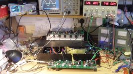
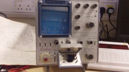
With no main output the opamp is open loop so a bit giddy, (proves the clip indicator works!) I've tacked a 100K across pin 1 and 2 to get a test sine wave established between D1 and D2. Dual trace scope (see opening pic) at the e of T11 and T12 can show +ve sine half on T11 and -ve sine half on T12 but only with asymmetrical fine tuning of the power rails (bench supply I'm not poking about with a 3000VA backed PSU) and D7 anode lifted. Once set it is repeatable, turning off/on takes a few seconds for the scope trace to drift back to equilibrium. I've temporarily tacked on a LED to show Mute operating, hardly a second at power up, longer at turn off and I checked, it comes on with a heat gun on the heat sink temp sensor.
How is this deceptively simple circuit of three stacked transistors T11,T13,T15 (T12,T14,T16) per rail supposed to work? I am intrigued by T13 and T14 separating the +-150V (approx with a rail switch) from the +/- 15V small signal operating environment for the opamp to play in.
If you have any advice or fault finding suggestions to help me get this going I will be very grateful. Many thanks.
Mr Chris
https://www.diyaudio.com/forums/attachment.php?attachmentid=944248&stc=1&d=1618919251
Googling W audio, Zenith 3000, prolight.co.uk (importer) got me the operator handbook no schematics so after drawing it up in Kicad, I was curious about one of the heatsink temperature sensors and Googling "90AR3U3" lead to a W_Audio_Zenith_3000_Schematic.PDF for the whole amp! (I just tried to repeat this and failed, cut and past the pdf string instead.)
https://www.diyaudio.com/forums/attachment.php?attachmentid=944249&stc=1&d=1618919251
My KiCAD drawn reverse engineered schematic is V1.0 the other found one for V1.5. To save you playing "spot the difference" they have replaced the triac crowbar with output relay and delay / DC detect circuit and gone to single emitter resistors, the rest of the amp appears to be the same.
On first look after lifting the lid, what jumps out is the absence of isolation pads between output transistors and heat sink. The heat sink is isolated from the case by a thin sheet of fibreglass and is at output potential.
The emitter current share resistors in V1.0 are paralleled pairs of 2W 0R68 and had all "silently" failed open circuit (no sooty skid marks!) is this a metal film failure characteristic?
The only evidence of explosion was a few TO92 with "plasma ejection holes" and charcoaled 1/4W resistors. Removing the PCB from heat sink revealed a few vaporised tracks.
I was hopefully expectant of success after searching and replacing all shorted transistors and diodes and open circuit resistors and missing PCB traces repaired but all to no avail. Both channels refuse to come back to life. I have "come a gutsa" and I am stuck.
Fault finding efforts so far:
With no main output the opamp is open loop so a bit giddy, (proves the clip indicator works!) I've tacked a 100K across pin 1 and 2 to get a test sine wave established between D1 and D2. Dual trace scope (see opening pic) at the e of T11 and T12 can show +ve sine half on T11 and -ve sine half on T12 but only with asymmetrical fine tuning of the power rails (bench supply I'm not poking about with a 3000VA backed PSU) and D7 anode lifted. Once set it is repeatable, turning off/on takes a few seconds for the scope trace to drift back to equilibrium. I've temporarily tacked on a LED to show Mute operating, hardly a second at power up, longer at turn off and I checked, it comes on with a heat gun on the heat sink temp sensor.
How is this deceptively simple circuit of three stacked transistors T11,T13,T15 (T12,T14,T16) per rail supposed to work? I am intrigued by T13 and T14 separating the +-150V (approx with a rail switch) from the +/- 15V small signal operating environment for the opamp to play in.
If you have any advice or fault finding suggestions to help me get this going I will be very grateful. Many thanks.
Mr Chris
Attachments
T15 & T16 are apparently mute inputs.
T11 & t12 look as if they are VI limiters with the R23 C14 network.
T13 &T14 are middle powered transistors, pre-drivers I believe.
T21 & T22 are the drivers.
D1 & D2 are the temperature sensors, should be mounted near the heatsink.
The "not economically repairable" statement from a pro means that if you don't pay the bill, he can't sell it for what his repair costs could be. "Zenith" is not a high status name in high powered amplifiers. Class AB is fairly obsolete if one is not sensitive to digital artifacts in the sound or transmitted to other analog devices. Bar bands are moving to class D which in 800-1200 W range weighs about 40 lb less than this class AB dinosaur. However class AB can be repaired by amateurs with a DVM and an analog VOM, and Class D cannot.
5 pairs MJL21195/96 parallel indicate possibly a 300 to 400 w/ch amp.
If you are rather inexperienced this high powered amp is a bad start. One slipped probe can burn the copper end off and throw molten copper around. Wear safety glasses. Use only one hand at a time, >24 v across your heart can stop it. Connect the meter negative to the analog ground with an alligator clip lead. Don't wear jewelry on hands arms or neck. 1 v through a ring can burn your flesh to charcoal. If you're starting out I would recommend an ebay $30 PV-4c or M-2600 for parts or repair (plus freight). I have a repaired 1300 W amp that I really don't have a use for. My audiences are not that big; a CS800s would be fine if I tripled my audience size. 70 w/ch is fine in my house for the cannon shots in 1812 overture, on 101 db 1w1m speakers. I just bought a low wattage M-2600 which when repaired will be 75 w/ch.
Your bench looks a lot more professional than mine, however.
Good luck.
Last edited:
@indianajo
Thank you for taking the time to look over the schematic and reply.
I agree with you, it’s a made in China ‘budget’ PA amp, the student has a collection of them, names like ‘Prosound’ and ‘skytec’, dead giveaway.
You’re right, I probably wouldn’t try to repair a class D.
I see the ‘foldback current limiting’ 1/5 of the total output to T17 (T18). This amp has an extra heatsink temperature sensor, NR1 so bias diodes D1 and D2 are just on the PCB.
As I mentioned I am running the main rails at +/- 75V from the bench PSU current limited to a few hundred milliamps to reduce potential mishap current. The big toroidal transformer is powered via the bulb (faintly glowing in the pic) for the aux supplies but the main rail rectifiers are disconnected.
I previously repaired a PV-2600 that had had a small explosion and fire on the rail switch MOFET due to a shorted output transistor. The crowbar triac had been some what overstressed and also needed replacing. With the success of that I did as you say, ordered another ‘spares or repair’ off ebay. I was looking forward to the fault finding exercise but on arrival it was fully operational! Imagine the crushing disappointment when the DJ connected up his replacement amp to find his speakers fried.
@sidsparks
Thanks for reading and replying, I measure 0.5mA DC between the pad and lifted D7 anode putting it back in circuit which is enough to destabilise the quiescent operating point flatlining the -ve half sine at T12 collector. Though new, I have had T21 and T22 back out and on an ancient Telequipment curve tracer to check they still look OK, they did.
The fragility of the operating point is definitely a fault symptom.
Have you any feel for what the standing current should be down the transistor chain?
I’ll post a schematic exert with measurements and scope traces, perhaps someone will spot something obvious.
Thanks again.
Mr Chris
Curve tracers are interesting for designing new products. They probably measure at 2 v, correct me if I'm wrong. What is interesting about used transistors, after the double diode test, is : what voltage can they resist? I've found that used amp transistors that measure okay at the 2 v of my DVM, leak with the base open at 12 v. I put a 47 k series 12 v wall transformer, series C to E of transistor under test, series ma or later ua scale of DVM. base is left open. Transistor flows 250 ua or so, it is broken down. Transistor flows 2 ua or less, it is not damaged. Reverse polarity c-e for pnp transistor.Though new, I have had T21 and T22 back out and on an ancient Telequipment curve tracer to check they still look OK, they did.
Techs in 3rd world countries do this test to every batch of new transistors, often at higher voltage. Leakers were substituted at the vendor or at the border for known good parts. Don't put more than 24 v from hand to hand.
Hi indianajo,
Yes, as you say it’s important to test suspect transistors at more realistic voltages and some curve tracers allow this.
Telequipment CT71:
https://www.diyaudio.com/forums/attachment.php?attachmentid=945330&stc=1&d=1619167664
The collector supply can adjust upwards of 1000V!
The lid on the ‘test fixture’ is safety interlocked to prevent mishap.
The manual has lots of caution notices, ‘care must be taken when increasing the COLLECTOR SUPPLY not to exceed the device dissipation’ etc.
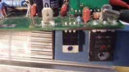
Anyway, some minor progress with the amp, I started to take measurements and the voltage across T15 c to e was only 0.15 and T16 was 1.1.
T15 out
https://www.diyaudio.com/forums/attachment.php?attachmentid=945331&stc=1&d=1619167664
Either I missed it double diode testing or popped it letting the PCB touch the heatsink, I’ve added a better plastic bag insulator and tiny cardboard box to lift the rail switch mosfets clear of the heatsink.
https://www.diyaudio.com/forums/attachment.php?attachmentid=945332&stc=1&d=1619167664
https://www.diyaudio.com/forums/attachment.php?attachmentid=945333&stc=1&d=1619167664
I briefly saw nice big sinewaves varying with input level control across R23 and R24 but by the time I reconnected the scope probe to look at the output pin it had stopped, the current draw on the the PSU meters dropping back from a few hundred milliamps to tens of milliamps. Something intermittent about it, I’ll keep at it.
Yes, as you say it’s important to test suspect transistors at more realistic voltages and some curve tracers allow this.
Telequipment CT71:
https://www.diyaudio.com/forums/attachment.php?attachmentid=945330&stc=1&d=1619167664
The collector supply can adjust upwards of 1000V!
The lid on the ‘test fixture’ is safety interlocked to prevent mishap.
The manual has lots of caution notices, ‘care must be taken when increasing the COLLECTOR SUPPLY not to exceed the device dissipation’ etc.
Anyway, some minor progress with the amp, I started to take measurements and the voltage across T15 c to e was only 0.15 and T16 was 1.1.
T15 out
https://www.diyaudio.com/forums/attachment.php?attachmentid=945331&stc=1&d=1619167664
Either I missed it double diode testing or popped it letting the PCB touch the heatsink, I’ve added a better plastic bag insulator and tiny cardboard box to lift the rail switch mosfets clear of the heatsink.
https://www.diyaudio.com/forums/attachment.php?attachmentid=945332&stc=1&d=1619167664
https://www.diyaudio.com/forums/attachment.php?attachmentid=945333&stc=1&d=1619167664
I briefly saw nice big sinewaves varying with input level control across R23 and R24 but by the time I reconnected the scope probe to look at the output pin it had stopped, the current draw on the the PSU meters dropping back from a few hundred milliamps to tens of milliamps. Something intermittent about it, I’ll keep at it.
Attachments
I learned something about curve tracers. Measuring voltage in circuit is quicker than removing them, if you have a light bulb box in series with the AC to limit the damage.
T17 measures the current on the emitter resistor of T23, a classic vi limiter function. But then it transmits the shutoff to T15, which switches the >100 v rail off to T13. That seems a rather risky duty for a 40 v 200 degC/watt 2n3904. I've found them fragile in other applications. If it wasn't for the lead layout and I was keeping the amp, I'd upgrade to a mje15030 or something. The part is only stressed when it is doing its job. As long as there is no problem with the speaker T15 rides along happily passing current to T13 with no stress.
T17 measures the current on the emitter resistor of T23, a classic vi limiter function. But then it transmits the shutoff to T15, which switches the >100 v rail off to T13. That seems a rather risky duty for a 40 v 200 degC/watt 2n3904. I've found them fragile in other applications. If it wasn't for the lead layout and I was keeping the amp, I'd upgrade to a mje15030 or something. The part is only stressed when it is doing its job. As long as there is no problem with the speaker T15 rides along happily passing current to T13 with no stress.
The KiCAD schematic has inputs und and outputs between the two OpAmps in NE5532 confused.
The above OpAmp of pins 1,2,3 does the clipping and muting calculation --> should feed the muting transistor T9.
The below OpAmp of pins 5,6,7 is the amp input stage and should be connected to D1 and D2.
T13 is a cascode of T11 which will mainly pull current through R41 (200R) from positive rail to control the driver (negative side likewise with T12, T14, ...).
T15 works as a switch and will disable the positive side in case of either mute or over-current condition. Muting is triggered by T9 and T19, while over-current turn-off is triggered by T17.
High thermal stress will be on T13 (cascode) and T21 (driver). This is where you might want to look for problems.
I wonder if this amp is Class G oder Class H, depends on the two ICs used to trigger the rail switch MOSFETs, I guess.
Class G normally has fast switching diodes or mosfets inline with the amplifier's power rails. These commutate the power supply voltage from 2 or more fixed +/- paired voltage power supplies according to preset thresholds of the input signal magnitude. It's simpler circuitry than class H which essentially, has continuously variable rail voltages which track the signal magnitude. What are the Different Types of Audio Amplifier Classes? | Audioholics
Last edited:
I sometimes resort to removing outputs and feedback driver output back into ltp.
This gives something that can be powered without exploding transistors.
You can then go through each stage checking voltages
I had a Maplin amp that was a pig to fix.
Went round and around and kept coming back to one transistor.
It diode checked ok but voltages on it werent right.
In the end it suddenly hit me that someone had put in a npn instead of a pnp transistor hence it diode checked ok ! Just to help the number had worn off.
I had even checked every component on the pcb.
Faults are hard enough to find sometimes but when someone has been in before you it can become a nightmare with wrong components and/or hacked tracks.
I found persistance pays off, my time costs me nothing and even if the amp is worth little the experience gained is valuable.
Another faulty amp didnt work right and I had to resort to checking each component again.
Turned out Farnell had sent wrong resistor in a bag.
It had 10k on the bag but was 100r !
@sidsparks
T13 (T12) yes, as you say, the datasheet indicates 20W but not mentioned is the TO220 shape and ‘no isolator required’ all plastic body.
I am so used to seeing signal to transistor base and output at collector so seeing the base to a fixed voltage rail confused me.
‘The New Penguin Dictionary of Electronics’ ISBN 014051.0745 tells me:
common-base connection Syn. Grounded-base connection. A method of operating a transistor in which the base is common to both the input and output circuits and is usually earthed. The emitter is used as the input terminal and the collector as the output terminal. This type of connection is commonly used as a voltage amplifier stage.
@poetry2me Thanks for looking in and playing ‘spot the difference’.
The ‘China’ Protel Schematic package (V1.5) comprises:
S1.pdf, schematic of input PCB.
SP1.pdf, component silk layer of input PCB,
S2.pdf, schematic of mains input/switching/transformer/rectifiers etc.
SP2.pdf rectifier and caps PCB silk layer.
S3.pdf the amp schematic.
SP3.pdf, Amp PCB component overlay silk layer.
S4.pdf the front panel LEDs and level pots.
S5.pdf Schematic of +ve railswitch.
SP5.pdf comp overlay of +ve rail switch PCB.
S6.pdf Schematic of -ve rail switch.
S6.pdf comp overlay of -ve rail switch PCB.
S3.pdf refers to IC1A and IC1B with output of A feeding between D1 and D2 same on Kicad schematic?
‘cascode’ , new terminology to me thank you. Had to wiki that, good stuff.
Hopefully T13 (T14) transfer sufficient thermal stress to the heatsink despite being all plastic. If they fail short circuit bad things will most definitely happen.
LM311 high-speed voltage comparators used in rail switch mini PCB modules.
The Kicad schematic shows (extreme RHS maybe you didn’t scroll far enough?), D15 (D16) with snubbers (C17 R57) to prevent the HV rail backfeeding to the LV rail when T33 (T34) MOSFETs switch, R90 C35 snubbers.
@Ian Finch Thanks for your reply, so, Class G then, as this uses a MOSFET to switch to a higher rail.
@nigelwright7557. Interesting what you say about ‘someone being in before you’. One of the amp PCB’s had +15V rail missing. It was obvious that the +ve reg had been replaced, scratches around the pins and flux residue. The reg I took out had that horrible font where an 8 and 9 can be confused. 79L15 had fitted instead of 78L15.
@epicyclic, Thanks for your post and for the standing current calc. I had checked all resistors, both channel R43's were OK, Both R44 had to be replaced though (OC).
I was so busy replying to posts I forgot a status update.
I think the board I was working on is ready to fit back to the heatsink. There is a heathy looking sine at the output, I had to turn up the current limit to 1A and with only one pair of output transistors fitted and nothing screwed to the heatsink I couldn’t leave it very long, Things soon start to smell hot. Remind me to remove the temporary opamp gain resistor.
I’ve put that channel to one side to try the other. So far no faulty TO92’s found.
I’m back on the first one. I was getting nowhere with channel 2 and the lure of seeing a working channel was too much.
It is all done up on the heatsink with the full complement of output transistors (pun intended), I took the extra resistor off the opamp.
I still have it at +/- 75V, current limited 0.6A, no dummy load yet. There is a good heathy output sine on the scope and, when winding up the level control, the clip indicator lights just as it flat tops to the rails.
But, it had been sitting there for a few minutes when over the fan noise of the signal gen and scope I heard a pop. Well not really a pop more a ‘click’. The output went off and the supply went into limit. Good job I hadn’t put it back on the main amp supply! I turned it off then on, straight into limit, off, pause, back on, same ‘click’ normal service resumed.
I’m thinking the crowbar triac randomly decided to short the output? Or it was made to by the SCR's? I had examined the triacs closely, I’ve seen them split apart after being fired off, but they look pristine and no heat induced colour change on the mounting tab. I’ll take it out and see if there is a reoccurrence of supply limiting. Maybe that’s why in amp V1.5 they replaced the crowbar with a relay? Are crowbar circuits known for bad behaviour?
One disconnects the crowbar triac or SCR until the amp is fully tested including a full load test until it heats up. Then having proved function you can reinstall the triac or SCR. Full load test requires load resistors; don't subject a speaker to a faulty +-140? v amp.
Actually when my 650 w/ch amp failed, it both took out the triac, and the diac that triggers the short. Had I not tested the diac the new triac would have never protected anything. SBS breaks down at 7 v in either direction,in my amp.
Actually when my 650 w/ch amp failed, it both took out the triac, and the diac that triggers the short. Had I not tested the diac the new triac would have never protected anything. SBS breaks down at 7 v in either direction,in my amp.
Hi indianajo,
Good advice to remove crowbar and perhaps even with no outward sign of stress replace it with new when done?
I suppose a test speaker could be AC coupled with a big home made bipolar cap from two electrolytic caps back to back?
I made a load resistor bank years ago for dummy load testing. It has four fan cooled cells each with four 200W resistors. The switches series/parallel pairs of cells and again to give single or dual channel operation. With all R’s in series and connected across 230V mains it has in the past doubled as extra workshop heating.
https://www.diyaudio.com/forums/attachment.php?attachmentid=946957&stc=1&d=1619615143
https://www.diyaudio.com/forums/attachment.php?attachmentid=946958&stc=1&d=1619615143
Anyway, traic removed, 4R dummy load, AVO reads just over 1A when the bench supply limits at 1A. The 1Khz test frequency is emanating from the PSU. I can just about keep the back of my finger pressed to an output transistor. After about 10 minutes the thermocouple that came with the DVM, is measuring 65C (150F) but I’m going to stop it as no fan on the heatsink, it’s still just on the bench.
How long do you soak test a repaired amp before declaring ‘it’s fixed’?
Back to channel 2.
Attachments
For elimination purposes I was thinking about lifting T11 and T12 collectors and connecting them to +/-15V expecting to see sines at their emitters.
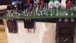
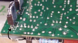
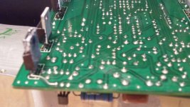
I was about to start de-soldering but spotted T14 emitter joint 'thin' on solder so continuity checked:
https://www.diyaudio.com/forums/attachment.php?attachmentid=948600&stc=1&d=1620114258
Added wire pad to pad:
https://www.diyaudio.com/forums/attachment.php?attachmentid=948601&stc=1&d=1620114258
It works now.
Just the crowbars to replace.
Attachments
Congratulations.
These high powered amp can burn the lands of the PCB's. I had to jumper 4 lands with 26 ga wire in my PV-1.3k. Blown outputs or drivers can supply more current out the base line than a PCB can stand.
Since I own my unit, I put fuses in the driver lines to the OT's and 3.3 v zener clamps to ground on the base lines to the drivers. Maybe won't blow 127 components next meltdown.
- Home
- Amplifiers
- Solid State
- Stuck repairing amp, Please help. Schmatic / Pics inc.