Well you have to use the 2 series transistors as used in the honey badgerI have the pre drilled 5U deluxe chasis
Well you have to use the 2 series transistors as used in the honey badger
The build guide used the MJL4302/4281AG
Its a simple story. If you use the UMS you have to use the 2 series transistors. If you drill and tap your own holes you can use the 4 series.The build guide used the MJL4302/4281AG
Very nice ...
Very nice Dadod. Yours and the Hellraiser could be prime candidates for
Kicad and SMD.
Or a combo.
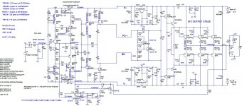
Have you thought of just injecting the servo FB into a split R7 to affect Vf
of D1/2 ??
Why the CCS cascodes ??
Also , 15 V regs are better as cold zener pass regs.
I'll have to show you my "Dadod hellraiser" your private .asc was assimilated
by the Borg.
OS
Very nice Dadod. Yours and the Hellraiser could be prime candidates for
Kicad and SMD.
Or a combo.
Have you thought of just injecting the servo FB into a split R7 to affect Vf
of D1/2 ??
Why the CCS cascodes ??
Also , 15 V regs are better as cold zener pass regs.
I'll have to show you my "Dadod hellraiser" your private .asc was assimilated
by the Borg.
OS
Question OS.
R19 schematic lists 33 ohms bom lists 47 ohms.
Which one is correct?
Both , depending on gain group choice of Q13. 100-150Hfe could be 27-33R,
200+ could be 47/56R.
Since we are CCS based on the wolverine , R19 is beta dependent.
OS
Badger /wolverine differences.
This was a major layout decision.
The Badger locates the Vbe inline with the OP and drivers. Great for an EF2.
EF2 is a relative "low Z" compared to a EF3. Wolverine OPS board needed
to have the Vbe contained to a smaller "private" area using another UMS hole
previously unused on the Badger.
Therefore the right angle mounting option you have with the Badger is
unavailable. Flat is the only way.
The multiple EF3 advantages outweigh this single drawback.
OS
Thanks for clearing that up OS.Both , depending on gain group choice of Q13. 100-150Hfe could be 27-33R,
200+ could be 47/56R.
Since we are CCS based on the wolverine , R19 is beta dependent.
OS
Please look at post #999
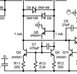
Have you thought of just injecting the servo FB into a split R7 to affect Vf
of D1/2 ??
Why the CCS cascodes ??
Also , 15 V regs are better as cold zener pass regs.
OS
Hi Pete,
I simulated this kind of injecting DC servo, bu came to conclusion that it sometime asks for to much opamp output voltage swing, so I stay with classic DC servo.
This CCS is temperature very stable and it's not cascode but current mirror, look a diodes D3 and D4 as transistors with base connected to the collector.
I prefer shunt over serial voltage regulator.
Damir
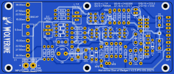
Wouldn't it be better if these traces were on copper bottom? View attachment 951701
I don't think it matters much since they aren't near the feedback ground point.
Thanks.I don't think it matters much since they aren't near the feedback ground point.
I asked this question because currently any return currents that return to the Actual power supply from the capacitors have to pass through the via's.
Also those traces which the capacitors are on is the same trace as the speaker return.
I would have thought that if they were just connected to the power supply trace it would save going through the via's
Ok, thanks, I'll change the trace that the capacitors are on to the same as the power supply ground.That makes sense.
Thanks for your time and support looking over that for me keantoken I really appreciate it.
Harry and I have been both reviewing everything with a fine tooth comb for just over a week now and we are just about done.
Thanks.
I asked this question because currently any return currents that return to the Actual power supply from the capacitors have to pass through the via's.
Also those traces which the capacitors are on is the same trace as the speaker return.
I would have thought that if they were just connected to the power supply trace it would save going through the via's
Those vias are 30A at 1oz and 50A 2oz ,each is 7A @ 2oz (.8mm x pi).
OS
Hi OS and other forum members,
Over the past two weeks Harry and I have been very busy going over the layout and B.O.M. with a fine tooth comb, checking everything we can think of.
In the process of doing this we found a few things that we felt could be improved and also a few creepage issues which we have now fixed.
We also added R0 100K across the input to prevent the input from floating.
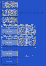
We have developed a project file to hold all the current layouts.
Below is a description of each layout.
1. Spooky V2.2 - Unchanged from OS last post.
Notes: This layout may or may not need a thorougher check as well. To be honest I haven't even looked at it.
2. Wolverine IPS V2.5 - Updated from V2.4 OS last post.
Notes: Full check and optimization done. All creepage, silkscreen and trace issue were checked and fixed as necessary.
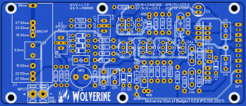
3. Wolverine IPS with current mirror helper V2.6 - Updated from V2.5
Notes: Added the current mirror helper to the V2.5 file as per attached image.
This was added as an option and does not need to be used. The board can be build just as the V2.5 board if the user chooses not to use the CM helper option.
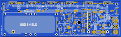
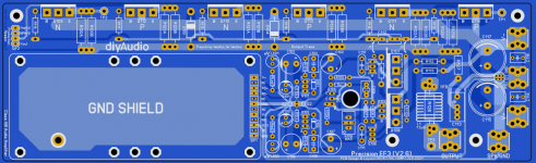
4. EF3 Layout V2.5- Updated from V2.4 OS last post.Notes: Full check and optimization done. All creepage, loop area, silkscreen and trace issue were checked and fixed as necessary. The NFB trace put onto copper bottom and SMD pads can be used. This should give the best isolation from the inductor.
4. EF3 Layout V2.6- Updated from V2.5
Notes: An idea I had for new layout for the PSU section which eliminates the main power supply traces running under the inductor and NFB trace.
The sprint files will be posted in a few days once we do a final check of the layouts against the schematic.
Harry and I offer these layouts to you and the other forum members. I hope they can improve the quality of the DIY Audio Stores products no matter which version you choose to submit.
Over the past two weeks Harry and I have been very busy going over the layout and B.O.M. with a fine tooth comb, checking everything we can think of.
In the process of doing this we found a few things that we felt could be improved and also a few creepage issues which we have now fixed.
We also added R0 100K across the input to prevent the input from floating.
We have developed a project file to hold all the current layouts.
Below is a description of each layout.
1. Spooky V2.2 - Unchanged from OS last post.
Notes: This layout may or may not need a thorougher check as well. To be honest I haven't even looked at it.
2. Wolverine IPS V2.5 - Updated from V2.4 OS last post.
Notes: Full check and optimization done. All creepage, silkscreen and trace issue were checked and fixed as necessary.
3. Wolverine IPS with current mirror helper V2.6 - Updated from V2.5
Notes: Added the current mirror helper to the V2.5 file as per attached image.
This was added as an option and does not need to be used. The board can be build just as the V2.5 board if the user chooses not to use the CM helper option.
4. EF3 Layout V2.5- Updated from V2.4 OS last post.Notes: Full check and optimization done. All creepage, loop area, silkscreen and trace issue were checked and fixed as necessary. The NFB trace put onto copper bottom and SMD pads can be used. This should give the best isolation from the inductor.
4. EF3 Layout V2.6- Updated from V2.5
Notes: An idea I had for new layout for the PSU section which eliminates the main power supply traces running under the inductor and NFB trace.
The sprint files will be posted in a few days once we do a final check of the layouts against the schematic.
Harry and I offer these layouts to you and the other forum members. I hope they can improve the quality of the DIY Audio Stores products no matter which version you choose to submit.
Attachments
Last edited:
Great job OS, Harry, Stuart and all the others - the incredibly short design/development cycle with such professional input from so many has been a joy to follow. Plus R0 addition is helpful and the current source helper is an option I will likely need as I only have lower grade transistor options in stock. Its also good to be able to fit either the TO3P or the TO247 outputs.
Many thanks.....I look forward to the build.
Many thanks.....I look forward to the build.
- Home
- Amplifiers
- Solid State
- DIYA store "Wolverine" (Son of Badger) .... suggestions ??