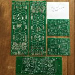
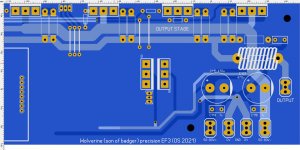
Been working on the new store amp.
The old "Honey Badger" is a nice amp.
But , it was such a long time ago. Like Windows XP .
.
It's 2021 , time for ....
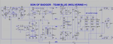
- EF3 (like a leach amp - or HK680) goodness.
- Ripple cancelling rail traces.
- P/N/P/N/P/N alternating output device genders - consistant thermals and
NFB takeoff nodes throughout.
- 2 X 2W-.47R per output device Re , or single MOS 5w 220mOhm ones.
- Cap multipliers.
- .5A +/- 12v aux. supplies with external output built in.
- Servo.
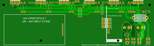
- And , A SIP connector for the ability to add any 20th century classic input
stage to this project. I you don't use the connector , the original Wolverine/
Badger (blameless) topology is default.
ALL these designs have not only been tested .... but some sell them on the
internet. I did a search of the "Slewmaster" WOW ! , there were a lot of images !
I have heard of the suggestions for left and right versions of the project boards.
It would be up to management to decide on 2 board runs ???
The tiny hole problem was unfortunate , but now I am researching the
parts individually as I do layout.
Any drawbacks ???
- Caps multipliers , you lose 2.1V per rail .... but gain 30db+ PSRR over
most of the audio spectrum. A quite simple circuit - needed for a CFA input stage.
- EF3 - lose another volt off the rails.
Any and all suggestions welcome ....
PS - if anyone has the EXACT output device spacing for the Badger store boards ... please share. I had to reverse engineer from the store PDF and
a simple toner transfer image I had . I lost my original artwork.
OS
The old "Honey Badger" is a nice amp.
But , it was such a long time ago. Like Windows XP
.It's 2021 , time for ....
- EF3 (like a leach amp - or HK680) goodness.
- Ripple cancelling rail traces.
- P/N/P/N/P/N alternating output device genders - consistant thermals and
NFB takeoff nodes throughout.
- 2 X 2W-.47R per output device Re , or single MOS 5w 220mOhm ones.
- Cap multipliers.
- .5A +/- 12v aux. supplies with external output built in.
- Servo.
- And , A SIP connector for the ability to add any 20th century classic input
stage to this project. I you don't use the connector , the original Wolverine/
Badger (blameless) topology is default.
ALL these designs have not only been tested .... but some sell them on the
internet. I did a search of the "Slewmaster" WOW ! , there were a lot of images !
I have heard of the suggestions for left and right versions of the project boards.
It would be up to management to decide on 2 board runs ???
The tiny hole problem was unfortunate
, but now I am researching theparts individually as I do layout.
Any drawbacks ???
- Caps multipliers , you lose 2.1V per rail .... but gain 30db+ PSRR over
most of the audio spectrum. A quite simple circuit - needed for a CFA input stage.
- EF3 - lose another volt off the rails.
Any and all suggestions welcome ....
PS - if anyone has the EXACT output device spacing for the Badger store boards ... please share. I had to reverse engineer from the store PDF and
a simple toner transfer image I had . I lost my original artwork.
OS
Attachments
Last edited:
Hi Pete,
Very good design, really like the ripple eaters.
Can I ask:
1. What is the performance effect by adding the cascode Q5/6?
2. Have you compared SQ with and without the current mmirror Q3/4?
3. Same as #1 for the trick Hawksford cascode Q12?
4. I normally set up slightly overdriven Vbe multiplier to bring back the quiescent a little at higher temps. What does Q103 for the simple Vbe multiplier, Q104?
5. Given the potential instability of EF3s and the high beta of the TTC004B/TTA004B, do you think it really is needed to go to an EF3 when an EF2 with say 15mA in the VAS stage would drive it well?
6. How do you dimension C112? I know the suckout caps make a few difference to SQ.
What's the GM and phase margin, and where is the pole?
I do not criticise, this is a good circuit, but I'm always trying to reduce part count!
HD
These are nice 5W .22ohm emitter resistors from Mouser.
https://www.mouser.com/ProductDetail/KOA-Speer/BPR58CR22J?qs=1He0yLMpldAHlXM/x8XqjQ==
https://www.mouser.com/ProductDetail/KOA-Speer/BPR58CR22J?qs=1He0yLMpldAHlXM/x8XqjQ==
Attachments
Pete,
Is this what you are looking for on the hole spacing? Check out page 6.
My vote is to keep the cap multipliers. If one doesn't want to use them they could put resistors in place of D101 and D102 with Q101 and Q102 not populated.
Jeremy
Is this what you are looking for on the hole spacing? Check out page 6.
My vote is to keep the cap multipliers. If one doesn't want to use them they could put resistors in place of D101 and D102 with Q101 and Q102 not populated.
Jeremy
Attachments
Hello there , how ya doin' .. Hugh.
1. Cascode = ability to use choice low voltage devices , more gain at hf .
With the cascode , I can push the bandwidth to 1.5mhz , more NFB at 20k.
As with the VAS cascode , Miller effect is reduced.
2. Current mirror with or without the Cascode makes for "Snappy" solid bass
and HF. This is possibly subjective , I run some (amps) like this on my subs.
3. The VAS cascode - miller effect of the BCxxx is reduced - ability to use the
BCxxx at very low Vce. The EF3 does not load the cascode down , like the EF2.
VAS cascode also self clamps ... a "blameless" shortfall. (below)
Q14 only runs at 3.2V , even a 70ma pulse is irrelevant.
4. Q104 is the main HS Vbe , Q103 either is sandwitched between naked
drivers or on a small HS. This allows the rapid thermal changes of the main
drivers to alter the main output vbe ratio. The Harmon Kardon does this ,
almost like slow "Thermaltrak" output stage behavior. Also settles nicely
to it's set bias - and stays there.
5 . Unstable . These old EF3 Japanese designs are the longest survivors.
I simulated this OPS in isolation.
Adding C103/104/110 + R112 limits RF FB within the (rail) loop.
I see a similar scheme with all the old Japanese
EF3's. The High Z of the EF3 just means you have to be careful with it's layout.
A close trace in the wrong place can be bad.
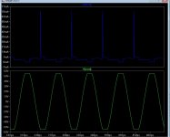
6. C112 - I observed the R111 current waveform and final THD with values between
.33u and 1uF. .68u was the sweet spot for R111=220r. Current waveform
becomes smoother at the right value. THD drops. I use 1uF for R111=150R.
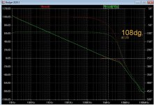
Phase = (below) 108dg. @ 1.22mhz UG. And that is with C4 - 68pF , R3/4
= 47R. Still under 10ppm/20K/2 or 4R load (EF3).
OS
1. Cascode = ability to use choice low voltage devices , more gain at hf .
With the cascode , I can push the bandwidth to 1.5mhz , more NFB at 20k.
As with the VAS cascode , Miller effect is reduced.
2. Current mirror with or without the Cascode makes for "Snappy" solid bass
and HF. This is possibly subjective , I run some (amps) like this on my subs.
3. The VAS cascode - miller effect of the BCxxx is reduced - ability to use the
BCxxx at very low Vce. The EF3 does not load the cascode down , like the EF2.
VAS cascode also self clamps ... a "blameless" shortfall. (below)
Q14 only runs at 3.2V , even a 70ma pulse is irrelevant.
4. Q104 is the main HS Vbe , Q103 either is sandwitched between naked
drivers or on a small HS. This allows the rapid thermal changes of the main
drivers to alter the main output vbe ratio. The Harmon Kardon does this ,
almost like slow "Thermaltrak" output stage behavior. Also settles nicely
to it's set bias - and stays there.
5 . Unstable
. These old EF3 Japanese designs are the longest survivors.I simulated this OPS in isolation.
Adding C103/104/110 + R112 limits RF FB within the (rail) loop.
I see a similar scheme with all the old Japanese
EF3's. The High Z of the EF3 just means you have to be careful with it's layout.
A close trace in the wrong place can be bad.
6. C112 - I observed the R111 current waveform and final THD with values between
.33u and 1uF. .68u was the sweet spot for R111=220r. Current waveform
becomes smoother at the right value. THD drops. I use 1uF for R111=150R.
Phase = (below) 108dg. @ 1.22mhz UG. And that is with C4 - 68pF , R3/4
= 47R. Still under 10ppm/20K/2 or 4R load (EF3).
OS
Attachments
Last edited:
Pete,
Is this what you are looking for on the hole spacing? Check out page 6.
My vote is to keep the cap multipliers. If one doesn't want to use them they could put resistors in place of D101 and D102 with Q101 and Q102 not populated.
Jeremy
Ohhh , thank you.
These are nice 5W .22ohm emitter resistors from Mouser.
Access to this page has been denied.
they would fit
Not bad , I have 16mm lead spacing X 2 for each output and SMD 11mm.
These SMD's are huge (10mm X 5mm) -
https://www.mouser.com/datasheet/2/418/5/ENG_DS_1773242_F-721591.pdf
.40 cents each. A great way for SMD scaredy cats to wet their feet.
The pair of leaded 16mm .5R x 2 would cost 12-14$ per board. $4.80 with
the SMD's. You can get some sub 1% 10mm .47R's for $1.20. metal oxide.
OS
Seems like servo's R204 could be a lot larger, less servo-hiss injection.
U2 output swing: up to +/-10V.
Worse-case offset of raw amp: 100mV.
R9 = 1k
So R204 could be 100k.
Spot on , I forgot to re-attach the servo - 97mv "raw"offset.
R204 at 27k reduced output noise from uV to a few nano volts. Good call.
Simulator clearly shows this. Servo at 2.2V ... why not use it.
Still under .5mv offset , any freq.
Hmm. Lost gain with higher servo Z. Made R2/R21/R204 all 27K. easy BOM !
OS
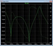
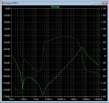
(below 1 is Badger PSRR). -74db/1Khz
(below 2 is with the multiplier). Hmm ... -110db/1Khz. Is this worth
2.1V ??
OS
Yeah that's a tough one, get rid of them if you're running out if board space.
Hi Pete,
What's the GM and phase margin, and where is the pole?
What? The "pole" here is an independent variable that has no bearing on the other two parameters. It makes little sense to ask about it in the context of the amplifiers stability.
It's the unity loop gain frequency (ULGF) which is important, not the open-loop bandwidth (the "pole" frequency). The former is fixed/determined by the input stage transconductance (gm), the value of the Miller compensation capacitor and the closed loop gain. It can be computed in less than two minutes from the component values shown on the schematic.
Unless we're to do something daft such as resistively loading the gain stages so as to kill the open loop gain and widen the open loop bandwidth to 20kHz or beyond, the "pole" frequency, on the other hand, is poorly defined and is influenced by, amongst other things, the Early Voltage performance of the small-signal transistors used.
I mentioned it in the other VFA/ CFA thread(and there is a good work around) , but since this is a suggestions thread...
Regarding the mounting of Q13(badger 2.4), the 5U deluxe UMS chassis, uses 2 lengths of heatsink, with a join directly in the center. Perhaps the wolverine can avoid this? I'd imagine new builders, who are intimidated to drill and tap may find this a deterrent.
The guide suggested a thermal bar, and AudioSan suggested mounting an aluminum strip along the heat sink join, and mounting to that.
Perhaps there is a way to compensate for this in layout?
Just a thought. I'm gonna go ahead and build it either way myself! Thanks for another exciting project!
Been working on the new store amp.
The old "Honey Badger" is a nice amp.
But , it was such a long time ago. Like Windows XP
I have heard of the suggestions for left and right versions of the project boards.
It would be up to management to decide on 2 board runs ???
The tiny hole problem was unfortunate
parts individually as I do layout.
Any drawbacks ???
- Caps multipliers , you lose 2.1V per rail .... but gain 30db+ PSRR over
most of the audio spectrum. A quite simple circuit - needed for a CFA input stage.
- EF3 - lose another volt off the rails.
Any and all suggestions welcome ....
PS - if anyone has the EXACT output device spacing for the Badger store boards ... please share. I had to reverse engineer from the store PDF and
a simple toner transfer image I had . I lost my original artwork.
OS
Hello OS. Many people claim that the XP is still the best operating system
I would like to see a layout like the sleewmaster with outputs on both sides. that eliminates the mirror board problems. That also means a 6 pair output option.
the 2.1V loss can be regaind by upping the sec voltage by 2 volts. use a 2x42V transformer instead of a 2x40V, and so on
outputdevice spacing for the honeyBadger is 40mm CC.
Last edited:
1) The original Badger's layout is optimal thermally.
2) The Slewmaster layout is better electrically, scales to a bigger output stages easier, and the driver transistors could be mounted on the main heatsink.
Jeremy
2) The Slewmaster layout is better electrically, scales to a bigger output stages easier, and the driver transistors could be mounted on the main heatsink.
Jeremy
Attachments
Last edited:
We are "up against" Pass Labs/burning amp/amp camp. We have to INTEGRATE
into the existing DIYA ecosystem.
Many of the low power 10-50W class A builders try a Badger ,
they have existing UMS cases.
Some PM me to ask about using their CRC PS 's.
I want to give them something that will "floor" them in the Class AB
topology.
I also would like to change to the dual row design , but I was told to conform.
It's easier to layout. I even have existing finished designs NOW.
As far as the Slewmaster , I noticed either the P channel or the N channel
would be offset in the bias. Top row would be hotter than the bottom.
I also had a vertical heatsink with the SM , top P/N pair would bias highest.
(Re higher mV) .
Same with drivers on the main HS , the slew's big TO-3P driver pair don't even need a heatsink.
I have the HK680 , just a pair of to-220's without heatsinks.
They need to have a fast thermal co-efficient for the 2'nd Vbe device (Q103) to be effective.
I need advice on the layout .
More pairs of eyes to double check for mistakes. , I will even submit the final .lay/gerber files.
Any advice on component choices would also be helpful.
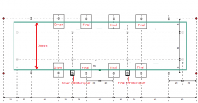
PS - output stage is set for 12.5A duty per rail , driver stage 2A .
Ground star is set. Center of star is tapped for secondary input stage grounds. (below).
OS
into the existing DIYA ecosystem.
Many of the low power 10-50W class A builders try a Badger ,
they have existing UMS cases.
Some PM me to ask about using their CRC PS 's.
I want to give them something that will "floor" them in the Class AB
topology.
I also would like to change to the dual row design , but I was told to conform.
It's easier to layout. I even have existing finished designs NOW.
As far as the Slewmaster , I noticed either the P channel or the N channel
would be offset in the bias. Top row would be hotter than the bottom.
I also had a vertical heatsink with the SM , top P/N pair would bias highest.
(Re higher mV) .
Same with drivers on the main HS , the slew's big TO-3P driver pair don't even need a heatsink.
I have the HK680 , just a pair of to-220's without heatsinks.
They need to have a fast thermal co-efficient for the 2'nd Vbe device (Q103) to be effective.
I need advice on the layout .
More pairs of eyes to double check for mistakes. , I will even submit the final .lay/gerber files.
Any advice on component choices would also be helpful.
PS - output stage is set for 12.5A duty per rail , driver stage 2A .
Ground star is set. Center of star is tapped for secondary input stage grounds. (below).
OS
Attachments
Last edited:
- Home
- Amplifiers
- Solid State
- DIYA store "Wolverine" (Son of Badger) .... suggestions ??