Hi Guy's just to add to what Jeremy said. Jeremy, myself, Harry and Johnno have been working on this in every spare moment that we have had.
Jeremy even went to the extent of measuring the trace inductance of the first prototype pcb on his network analyser so we could incorporate those measurements into the simulator.
The drivers have been changed to MJE15032G and MJE15033G and proper heatsinking has be calculated tested and implemented on the new pcb. All in all the new pcb is far superior to the last.
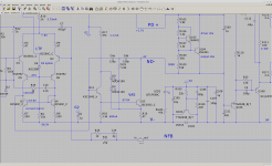
I will post an updated schematic tonight
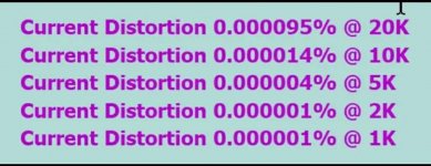
Distortion is also lower.
Jeremy even went to the extent of measuring the trace inductance of the first prototype pcb on his network analyser so we could incorporate those measurements into the simulator.
The drivers have been changed to MJE15032G and MJE15033G and proper heatsinking has be calculated tested and implemented on the new pcb. All in all the new pcb is far superior to the last.
I will post an updated schematic tonight
Distortion is also lower.
Last edited:
Welcome to the threadSubscribed ��
Still WIP at this stage as no prototypes have been made at the moment. I only just finished and ordered the pcbs yesterdayI guess I'm dense, but what build guide...?")
Okay Stuart, I went back and read the thread start to finish, I even understood parts of it. I would be happy to donate toward the next PCBs. I don't have a great skill set for testing, but would be willing to build a board if you think it useful. Otherwise, I'll donate to the cause because I think this could be a very good amp, the Badger is my main lab amp and I love it.
Perhaps the most useful thing I can add is this. In one post on the silk there was a Wolverine and version plus under it was (Son of Badger) I would suggest a change to Wolverine.XX SOB or perhaps Wolverine 2.1- SOB You get it.
If I can be any help, use me, I do have some test equipment, as you know and could work with you to verify or test.
JT
Perhaps the most useful thing I can add is this. In one post on the silk there was a Wolverine and version plus under it was (Son of Badger) I would suggest a change to Wolverine.XX SOB
or perhaps Wolverine 2.1- SOB You get it. If I can be any help, use me, I do have some test equipment, as you know and could work with you to verify or test.
JT

Badger
I would have been happy with resized hole sizing with Badger which is how we got Ostripper back to the forum when sent request for large resister holes and need for original files
Everything is still moving along... We found some mechanical alignment problems, lead spacing of components, hole sizing, and the big one - the driver not wanting turn off properly without turning the predriver into a space heater. We felt it was necessary to fix these issues on the pass 2 prototype and forget about building the pass 1. The design overall is much improved and I believe we are ready to order boards again. Sorry for the delay and not keeping everyone up to date.
I would have been happy with resized hole sizing with Badger which is how we got Ostripper back to the forum when sent request for large resister holes and need for original files
We found ... the driver not wanting turn off properly without turning the predriver into a space heater.
Oooh neat a space heater. Toasty
Could you say more about this -- how did the problem present itself and how did you address it?
Maybe this isn't the right thread for this anymore, now that y'all have made it so far along with real boards (which is awesome!)
Here's an improvement to the TPC build option. It reduces distortion a couple of dB in the treble range. It doesn't require adding any elements, it's just a connection change: instead of bringing the TPC resistor to ground, connect it to the VAS emitter.
This reduces the nonlinear current that the IPS must feed into the TPC network: voltage on both sides of the first TPC cap now "bounce" along with the nonlinear voltage at the VAS emitter so they cancel.
This doesn't affect stability margin. Just cleans things up a bit without changing how the circuit works. I didn't even change any component values. Sometimes it's the simple things
Attachments
Last edited:
Oooh neat a space heater. Toasty
Could you say more about this -- how did the problem present itself and how did you address it?
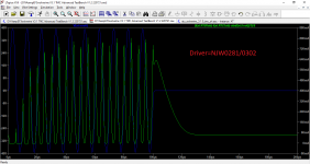
For the plots taken below:
-100kHz, 10 cycle burst
-Predriver bias resistor=910ohms
-Driver bias resistor=91ohms
-Cap across Driver bias resistor=1uF
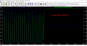
The green trace shows the cross conduction in a pair of output transistors. I did some math to remove the signal from the bias, so you are left with the dynamic bias between pairs. During the zero crossings the bias through both transistors should be about the same as the idle current.
Notice how the cross conduction in the outputs is worse with the NJW0281G and NJW0302 when they are used as the drivers because they are not getting shut off properly by the predriver. The cross conduction problem can be resolved by lowering the predriver bias resistor and adding a .1uF cap in parallel with it but then the predriver transistors are dissipating a lot of power for a TO-126.
Changing the driver to the MJE15032/33 eliminated these issues and keeps the predriver much cooler. Using NJW0281/0302's for drivers is unnecessary to drive 3 pairs of outputs anyways, more like overkill.
Jeremy
Attachments
Maybe this isn't the right thread for this anymore, now that y'all have made it so far along with real boards (which is awesome!)
Here's an improvement to the TPC build option. It reduces distortion a couple of dB in the treble range. It doesn't require adding any elements, it's just a connection change: instead of bringing the TPC resistor to ground, connect it to the VAS emitter.
This reduces the nonlinear current that the IPS must feed into the TPC network: voltage on both sides of the first TPC cap now "bounce" along with the nonlinear voltage at the VAS emitter so they cancel.
This doesn't affect stability margin. Just cleans things up a bit without changing how the circuit works. I didn't even change any component values. Sometimes it's the simple things
Good idea we are already looking at that. Too bad we just ordered pass 2 prototypes... We can get that into the final version hopefully.
On your schematic, I'd change Q12 to a low VCE and high beta transistor.
Jeremy
To add to what Jeremy said.Oooh neat a space heater. Toasty
Could you say more about this -- how did the problem present itself and how did you address it?
The original driver transistors that OS has planned to use work have required a heatsink that would have not have fitted in the space we had available. Not even close. So the transistors change was a necessity.

- Home
- Amplifiers
- Solid State
- DIYA store "Wolverine" (Son of Badger) .... suggestions ??