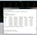
OS, this bode plot does not look like two pole compensation.
This is what I've got with my OITPC compensation (kind of TPC).
Yes , got that (2 phase humps) on the first run. I thought something was wrong ...
moved the feedback point to the other side of the probe.
OS
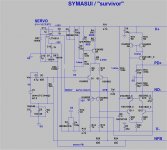
Look at the schematic below for examples of 1) and 3).
The bias leg on the left shows my preferred way of biasing an input cascode. I'm using IR LEDs instead of diodes, but the idea is the same. Those IR LEDs are 1.25V each at 2mA. So, that's about like 4 regular diodes.
My EF triple shows an example of the flipped-over pre-driver. The pre-driver runs at nearly constant current, so it's current does not have to be very high. Flipping the pre-driver gives you another VBE at each end of the voltage swing. It also seemed to give me slightly lower OPS distortion.
You are beating me on THD. I'm seeing at 100W about 3ppm up to about 2 kHz, and rising to 15 ppm at 20 kHz. I'm still working on lowering THD. As I said before, nice work. I really like your Wolverine amp.
Thank you , I looked over your circuit. I see what you are trying to do with
the cascode. I like your amp design , too. Like my "symasui" (below 1). Symasui is like the HK680 - as is the slew triple EF.
Playing around with the cascode (diodes /resistor/no buffer) seems to
have little effect on THD.
What does have effect is the ratio/value of the 2 pole (TMC) caps + OPS FB.
I was able to shift that .00002% "no THD" zone up or down.
Going too high made my SQ wave ring.

Where it is between 5-15Khz seems to be the most useful.
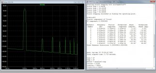
Who cares about 4ppm 3R 20k ?? Ha ha (Below 2).
Interesting that odd harmonics dominate .... at -112db
.FFT at 10k is below the simulator floor. This must of been what that English
builder did to his to get his real world 5ppm (AP test).
OS
Attachments
Last edited:
If the board is mounted properly with the output devices mounted to the lower side of the heatsink there isn't really any advantage to having the VBE transistor located closer to the output devices. We've tested this many times in the Slewmaster amp. This is the best thermal tracking design I've ever seen.
Thanks for that link and diode tip. I don't want run all those traces. I'll just
link out 2 Re's so they can use (whatever .. ebay/etc.).
You are right about the tracking , I put my (old) amp from the snowbank to the
washroom with only a few mA change.
Even if Q104 would be under compensated by a cooler spot on the HS , the drivers would heat slightly and change that comp. (thanks to Q103).
That is why for this design I will cluster Q103 as close to the drivers as possible.
OS
Nor would I expect it to. Any effects would be subtle. Saved a resistor. Might give a subtle improvement in AC performance, too. Hard to say. The output impedance of the cascode is a little higher if the impedance at the base is lower.Playing around with the cascode (diodes /resistor/no buffer) seems to
have little effect on THD.
Absolutely. You are boosting the loop gain by lots of dB at the higher audio frequencies. I'm glad you have been open to everyone's advice. You have started with a really nice amp and made it great.What does have effect is the ratio/value of the 2 pole (TMC) caps + OPS FB.
I was able to shift that .00002% "no THD" zone up or down.
OS
Thanks you ... yes, nice amp ... down boy !
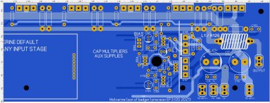
Needs a nice layout (below).
Driver stage /vbe / RC filters done. Enough room for cap mults/ 12V aux.
regulators.
The cap multipliers seem to be sufficient for the job ... just use 220uf caps
instead of 47's if you feel (tweeky/anal).
Questions -
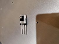
- Is a TO-126 package pinout always reverse from a TO-3p ?
Will a TO-126 stand high enough (lead length) to bolt to a mounted TO-3p ? Do TO-3p/126 both use
M3 bolt size ? - I want to bolt Q103 to the back of Q107.
- Like it says on the board , I will make the 12V supplies right next to the
Cap multipliers. Any accessory module will have -
(+12V / +60V / PD+ / GND/ NFB / ND- / -60V / -12V ) there is my 8 pin SIP.
I have so much room .. could I make a simple/better 12V regulator than the
zener pass reg. I've posted ?? Any suggestions ?
- (important) Since I have P/N alternating outputs , can my NFB take off be midpoint from between any pair ??
OS
Needs a nice layout (below).
Driver stage /vbe / RC filters done. Enough room for cap mults/ 12V aux.
regulators.
The cap multipliers seem to be sufficient for the job ... just use 220uf caps
instead of 47's if you feel (tweeky/anal).
Questions -
- Is a TO-126 package pinout always reverse from a TO-3p ?
Will a TO-126 stand high enough (lead length) to bolt to a mounted TO-3p ? Do TO-3p/126 both use
M3 bolt size ? - I want to bolt Q103 to the back of Q107.
- Like it says on the board , I will make the 12V supplies right next to the
Cap multipliers. Any accessory module will have -
(+12V / +60V / PD+ / GND/ NFB / ND- / -60V / -12V ) there is my 8 pin SIP.
I have so much room .. could I make a simple/better 12V regulator than the
zener pass reg. I've posted ?? Any suggestions ?
- (important) Since I have P/N alternating outputs , can my NFB take off be midpoint from between any pair ??
OS
Attachments
Last edited:
Looking good so far! In theory feedback should always be taken from the output point, that's what you will be hearing so that's what it should be correcting. I've never actually taken the time to actually test this though, I doubt it makes much of a difference.
It looks like you're using .400" centers for your resistors. That's a bit short for 1/4W. It means tight bends with no room for thermal expansion. Could lead to fractured resistors over time.
You could stretch out the lead centers on the base resistors for the outputs and move the traces to the other side of the output rail. That would loose a couple jumpers. Leads are a mile long on 1/2W resistors normally.
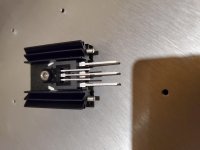
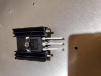
Those heatsinks can take a beating with no damage to the drivers. Work good but take a lot of board space.
I was just thinking of using one of them, a TO-3P driver on each side with the TO-126 on one side and mounted in front all using the same screw.
I use Russian software. Res500 for 1/4w = 1/2" lead centers. I think that's military spec too.
Who's military ??
BTW , 1/8 watt can be used anywhere I drop an 8mm macro. the ones I am concerned about are the 12mm/16mm.
I will handle the PDF "bible" for this creation , as well.
PS - I lost my macro library , as well.. I stole all the "slewmaster arcwelder" macro's to do this.
OS
Last edited:
150mils or 3.8mm
Have you considered something like this? Mouser part number is 532-513102B25. The small heatsink can be soldered to the board via the two pins.
Cool , nearly 4mm + 2mm for the AL plate (HS).
After looking to a "badger search" , the photo's showed many just using
junkbox parts and hardware around the world.
Same thing with Slewmasters in Indonesia.
Many do not have Mouser / digikey access.
I even actually degrade my simulations with ksa 92/42 pairs and MJE340/50
pairs to assure good "singing" in faraway lands.
OS
.41 -.64mm = 1/8 -1/4 w
.64 - .9mm = 1/2 - 1w
to 1.17mm - big resistors.
Jason stressed to not make small holes again !!
OS
I believe on the original badger you layed it out as a single layer board (bottom layer only). When they ordered the official boards they added the top layer copper to eliminate jumpers, all the holes were plated at the same time making their diameter unintentionally smaller.
Last edited:
- Home
- Amplifiers
- Solid State
- DIYA store "Wolverine" (Son of Badger) .... suggestions ??