Great improvement

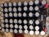
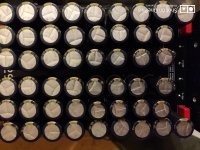
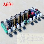
That is a great improvement because these on-board capacitors are too little to provide enough clean power for such a powerful output stage.
Furthermore, I intend to replace all 0R1 emitter resistors with 0,22 ohm to prevent thermal runaway at higher bias currents.
Very good Erlend,View attachment 932827 Two of this for my Accuphase Clon. If to meatless I will use Kendeil 180.000 uf 63 v.
That is a great improvement because these on-board capacitors are too little to provide enough clean power for such a powerful output stage.
Furthermore, I intend to replace all 0R1 emitter resistors with 0,22 ohm to prevent thermal runaway at higher bias currents.
Here is conversation from another thread that belong here:
All heat it generates pays-of with great sound. This amp is hot like Krells but has much more delicate sound. Awesome!
What you do is the right way to go. The cost of the amplifier board itself is just a fraction of investment into adequate power supply and heat sinks required to extract the maximum performance from this amplifier.
Also, it is a great idea to use a single 4 X 36 vac transformer. This means you can use a single larger transformer and yet keep the channels entirely separated. The chosen transformer has four secondaries - two for each channel. Perfect.
Indeed K-amps,Yes... A-60 runs quite hot !
I like its warm detailed sound though
All heat it generates pays-of with great sound. This amp is hot like Krells but has much more delicate sound. Awesome!
Erlend,I can't wait to my 4 X 36 vac 1500 w transformer arrives from Polen.
What you do is the right way to go. The cost of the amplifier board itself is just a fraction of investment into adequate power supply and heat sinks required to extract the maximum performance from this amplifier.
Also, it is a great idea to use a single 4 X 36 vac transformer. This means you can use a single larger transformer and yet keep the channels entirely separated. The chosen transformer has four secondaries - two for each channel. Perfect.

Last edited:
Could you buy the clones and just mod them? Win-win situation
The enterpreneur that sold the clone will be the real winner
Hei Rallyfinnen,Could you buy the clones and just mod them? Win-win situation
This board is really easy to tweak: bias & DC offset potentiometers are already on board. All you have to do is to adjust the desired values. Other possible improvement is adding more capacitance to the power supply section.
It would be indeed difficult to achieve substantial improvements on this board because there is absolutely almost no room for improvement. Just observe the measurements I have presented a couple of pages back. Awesome performance and great sound can be achieved almost with zero effort.
However, I guess you prefer more problematic boards where you can work more creatively.
Hello everybody! Today I ordered 2 power amplifier boards in the official store WEILIANG AUDIO, A60 +. And also 2 voltage transformers of 500VA at 2x36V. So take me into your ranks if there is no objection. Permission to ask questions. How bad are the onboard power transistors and power supply capacitors? Please forgive me for my English, I use a translator.
An externally hosted image should be here but it was not working when we last tested it.
Attachments
Last edited:
Hei Rallyfinnen,
This board is really easy to tweak: bias & DC offset potentiometers are already on board. All you have to do is to adjust the desired values. Other possible improvement is adding more capacitance to the power supply section.
It would be indeed difficult to achieve substantial improvements on this board because there is absolutely almost no room for improvement. Just observe the measurements I have presented a couple of pages back. Awesome performance and great sound can be achieved almost with zero effort.
However, I guess you prefer more problematic boards where you can work more creatively.
I have finnished the amp but can't find how to measure bias. Seems I turn and turn the pot but not much happens. Where is the "bias point". I am not able to locate it. Do you turn it anti clockwise to turn it up or clockwise? Is the relay open when diode is lighting or not?
Hi my dear Friend,I have finnished the amp but can't find how to measure bias. Seems I turn and turn the pot but not much happens. Where is the "bias point". I am not able to locate it. Do you turn it anti clockwise to turn it up or clockwise? Is the relay open when diode is lighting or not?
I am sorry Erlend for delayed response, I've been busy with a trio of MJL boards these days.
Observe the board from above and locate "Test" point. It is in the vicinity of the negative side of the 2nd smoothing capacitor. There are two holes, very convenient to measure with one hand and adjusting the potentiometer with another. For me it is a piece of cake because I am an ambidexter (I use both hands equally without having to be aware what is left and what is right).
I do not remember the direction that increases the bias, but try slowly by revolving the potentiometer in both directions for 1/8 of the turn. Then proceed, but slowly and carefully. Otherwise there may be smoke in the roof of your house.
I am glad you're achieving your yet another goal.

Last edited:
Hi my dear Friend,
I am sorry Erlend for delayed response, I've been busy with a trio of MJL boards these days.
Observe the board from above and locate "Test" point. It is in the vicinity of the negative side of the 2nd smoothing capacitor. There are two holes, very convenient to measure with one hand and adjusting the potentiometer with another. For me it is a piece of cake because I am an ambidexter (I use both hands equally without having to be aware what is left and what is right).
I do not remember the direction that increases the bias, but try slowly by revolving the potentiometer in both directions for 1/8 of the turn. Then proceed, but slowly and carefully. Otherwise there may be smoke in the roof of your house.
I am glad you're achieving your yet another goal.
Thanks for answering. Playing now and it's really a fantastic amp Berlusconi.
dear Berlusconi.
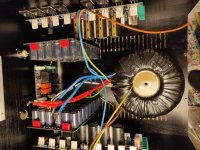
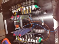
I got a case, amplifier boards, soft-start board for aliexpress. But in the photo of the seller's website there is no layout of the internal space of the power amplifier. I would like to ask you or other respected high-quality sound lovers to take a photo of the insides of the power amplifier from different angles. This will help me to correctly position the components inside the case. Thank you in advance.
I got a case, amplifier boards, soft-start board for aliexpress. But in the photo of the seller's website there is no layout of the internal space of the power amplifier. I would like to ask you or other respected high-quality sound lovers to take a photo of the insides of the power amplifier from different angles. This will help me to correctly position the components inside the case. Thank you in advance.
- Home
- Amplifiers
- Solid State
- A60(+) Amplifier. Build this?
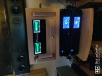
 Enjoy the Sound - you've deserved it dear Erlend.