Dear vmk2002,
I am working now on another project but will help you to assemble your amplifier. Mine is temporary disassembled but Erlend may make several snapshots of the inside of his impressive machine.
I have another set of photos to provide you guidance to assemble the amplifier. You will see.
I have some additional obligations these days but I will provide you with instructions how to connect individual components into a functional amplifier.
I will get back to you in few days, probably during May 1st vacations.
Meanwhile, fix the boards on heat sinks. Make 3mm threaded holes for each transistor. Be careful and use lots of lubrication, otherwise you may ruin your expensive heat sinks.
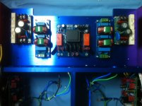
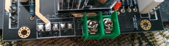
Also, you will need a small 12VAC transformer as auxiliary power supply for the internal speaker protection. Protection is on-board but needs 12 VAC external supply. On the image below you may observe connections to the boards.
@Erlend, please provide photos of the internals for our colleague.
Have a pleasant day
I am working now on another project but will help you to assemble your amplifier. Mine is temporary disassembled but Erlend may make several snapshots of the inside of his impressive machine.
I have another set of photos to provide you guidance to assemble the amplifier. You will see.
I have some additional obligations these days but I will provide you with instructions how to connect individual components into a functional amplifier.
I will get back to you in few days, probably during May 1st vacations.
Meanwhile, fix the boards on heat sinks. Make 3mm threaded holes for each transistor. Be careful and use lots of lubrication, otherwise you may ruin your expensive heat sinks.
Also, you will need a small 12VAC transformer as auxiliary power supply for the internal speaker protection. Protection is on-board but needs 12 VAC external supply. On the image below you may observe connections to the boards.
@Erlend, please provide photos of the internals for our colleague.
Have a pleasant day
Attachments

Berlusconi Hi, I didn’t disappear, it’s just that household chores take more time, but I read all the time.") vmk2002 Put here a photo of the case (dimensions) what kind of boards you have and radiators. The button is connected (on the board on the right) AC switch.
vmk2002 Put here a photo of the case (dimensions) what kind of boards you have and radiators. The button is connected (on the board on the right) AC switch.
vmk2002 Put here a photo of the case (dimensions) what kind of boards you have and radiators. The button is connected (on the board on the right) AC switch.Attachments
the case and the board are not yet coming from China (I'm trying to get the case from the seller in a completely black color, I paid, I'm waiting for the shipment). The transport company promises to bring transformers and boards with transistors on May 2. A case with indicators, but it looks like you also need a board to control them. The Chinese man does not understand me well, but I understand him . If someone has a complete amplifier A60 +, please post a photo inside the amplifier and a photo of the indicator control board (so that I can buy it in China). Thank you in advance. I have an impatient temper, so I apologize. I attach a photo of the case from the site and the board.


. If someone has a complete amplifier A60 +, please post a photo inside the amplifier and a photo of the indicator control board (so that I can buy it in China). Thank you in advance. I have an impatient temper, so I apologize. I attach a photo of the case from the site and the board.Dear vmk2002,
I am working now on another project but will help you to assemble your amplifier. Mine is temporary disassembled but Erlend may make several snapshots of the inside of his impressive machine.
I have another set of photos to provide you guidance to assemble the amplifier. You will see.
I have some additional obligations these days but I will provide you with instructions how to connect individual components into a functional amplifier.
I will get back to you in few days, probably during May 1st vacations.
Meanwhile, fix the boards on heat sinks. Make 3mm threaded holes for each transistor. Be careful and use lots of lubrication, otherwise you may ruin your expensive heat sinks.
Also, you will need a small 12VAC transformer as auxiliary power supply for the internal speaker protection. Protection is on-board but needs 12 VAC external supply. On the image below you may observe connections to the boards.
@Erlend, please provide photos of the internals for our colleague.
Have a pleasant day
Ok I will tomorrow or Friday.
Problems with the previous post.
Transformer:
https://aliexpress.ru/item/40000797...MIt6GuzYCe8AIVmal3Ch2qag_5EAkYAiABEgIsofD_BwE
Case:
https://aliexpress.ru/item/33037850...MIt6GuzYCe8AIVmal3Ch2qag_5EAkYAiABEgIsofD_BwE
PCB:
https://aliexpress.ru/item/32815366...h2qag_5EAkYAiABEgIsofD_BwE&sku_id=64631283545
Does it make sense to buy these "pots"?
https://aliexpress.ru/item/32507259...h2qag_5EAkYAiABEgIsofD_BwE&sku_id=57174709491
OK,
But first promise me that you will be very careful with setting the bias current (Read this: Wiki Biasing). Perhaps it is too early to talk about that but in this case it is better to be too early than too late. If you aren't careful with bias you may burn your power transistors on small heat sinks.
Caution, OK?
Today I have been investigating my A60+. There is design error that should be corrected, otherwise thermal run-away is possible.
The bias transistor 669A is located above the board and can not sense and compensate bias according to the increase of the power transistors temperature. Therefore, as the temperature of output power transistors increases, bias transistor remains approximately at the ambient temperature. As temperature of heat sink increases, current through the power transistors will increase and further increase temperature. The bias transistor should provide negative feedback based on increased temperature.
Solution is to de-solder the 669A transistor and solder it below the PCB so that it is connected and fixed to the heat sink just like the power output transistors. Be careful with 669A transistors if you have to purchase new device. Some of them aren't plastic and you have to isolate it with mica or alumina.
I bet your 669A is at the right place, fixed on the heat sink.
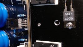
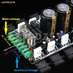
However, I have purchased a kit with misplaced bias transistor. In this kit version the 669A transistor is soldered above (please, see the attached snapshot), without contact to heat sink and there is huge risk of thermal runaway. To achieve safe operation I had to relocate the top-mount 669A transistor. Now, after re-soldering it is at the right place to adjust bias according to temperature rise.
On the attached snapshot you may see also temperature switch thermostat fixed to the heat sink which automatically turns of the entire amplifier if temperature approaches 75°C. Safe is safe.
I have similar, but a bit smaller heat sink 0.3W/C(300X200X45mm), and I have maximum 52°C. It is large enough to handle the heat at constant continuous 80W output of 25Vrms 1KHz sinewave into 8 Ohm load.
For example, today I have measured 42 mV initial bias at room temperature, 24°C. After a quarter an hour, under constant 80W load temperature has increased to 50.2°C steady state but the bias value has reduced to 30,8 mV. This indicates that the negative feedback works properly now.
Without relocation of 669A transistor on heat sink, the temperature would have gone further up, perhaps towards destruction of output transistors.
And, by the way, have a pleasant week end.
Attachments
Last edited:
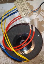
Hello everyone! Finally I received a package with transformers and transistor boards. I checked the transformers, it turned out like this: blue wires are 36VAC, black is the middle point of 36VAC windings, two yellow wires are 12VAC, two red wires are 230VAC primary winding.
Last edited:
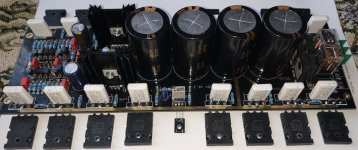
The photo shows the absence of a terminal block for powering the board. Does everyone have it? Also wondering which is more efficient, an aluminum oxide or mica heat-conducting insulating pad? The Chinese man sent me from mica, but I have from aluminum oxide. As I understand it, you need to connect 36V-0V-36V to the points of the board marked as AC-0-AC, and 0V-12V is needed to the AC-0 (no matter which of the wires with 12V is left or right)? I would be grateful for your answers, and yes, I will not connect without radiators (while the case is on the way) ...
Attachments

Last edited:
It is new version 1.2, mine is 1.1.vmk2002 make the board the largest, they are different
@vmk2002
Do not hurry.
First verify voltages on the transformer and,
Second: very important: MAKE A CURRENT LIMITING DEVICE: look here:
Build Your Own Current Limiter for Protection when Repairing and Testing Electronic Equipment
Third
Learn how to tap threaded M3 holes into aluminium.
Do not touch your chasis before you are confident and sure that you can make all 16 holes without error. One error is the end because you will need all your threaded holes. 15 isn't enough - each and every hole must be good. On your heat sinks you do not have enough place to repeat.
You will need one 2.5mm drill bit and three M3 tapping drills to complete this important task.
Look here:
Drill and Tap a Hole
and here:
Hand Taps & Proper Tapping Techniques - The Tool Corner
Also: Alumina is better.
You are correct regarding the AC connections. You can use any other similar terminals but select the one with adequate distance between the holes.
Last edited:
- Home
- Amplifiers
- Solid State
- A60(+) Amplifier. Build this?