Hello gang!
I am still very much a novice! And that's why I'm here needing help. Unfortunately. But this is a good place still!
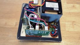
I have an old Klipsch ProMedia 2.1 PC speaker setup with 2 2way satellites and a subwoofer. Love it and IMO, worth reviving!
A couple years ago the foam surround on the 6.5" sub woofer speaker crumbled and everything else was still fine. Used it anyway.
A few months ago, I decided it was time to enjoy all of its capable frequency range again and bought a refoam kit and got it done.
Seemed like nothing was happening. Recently, I went in and tested the Sub Speaker amp terminals for DC voltage and thankfully, it was zero. Then with a signal (song) i Measured the AC voltages varying the Volume and Bass pots. voltage ranged with both pots low at 0.011 to both pots very high to 3.+ volts. and the voltage increased as I swept range through both pots.
After attaching the speaker again, it has non distorted output, just very low, and just a little louder with both pots turned way up.
I also have since gotten a new OEM speaker and there is no audible SPL difference.
I have a DMM (no scope) and I am hoping you guys can recommend how to find what or which stage or whatever is allowing signal to pass, just not amplified. And hopefully, a little explaining on how, as signal tracking isn't anything I've done before.
Schematics are linked below. Any help would be greatly appreciated! Thank you all!
Klipsch Promedia V2.1 Amplifier Repair
I am still very much a novice! And that's why I'm here needing help. Unfortunately. But this is a good place still!
I have an old Klipsch ProMedia 2.1 PC speaker setup with 2 2way satellites and a subwoofer. Love it and IMO, worth reviving!
A couple years ago the foam surround on the 6.5" sub woofer speaker crumbled and everything else was still fine. Used it anyway.
A few months ago, I decided it was time to enjoy all of its capable frequency range again and bought a refoam kit and got it done.
Seemed like nothing was happening. Recently, I went in and tested the Sub Speaker amp terminals for DC voltage and thankfully, it was zero. Then with a signal (song) i Measured the AC voltages varying the Volume and Bass pots. voltage ranged with both pots low at 0.011 to both pots very high to 3.+ volts. and the voltage increased as I swept range through both pots.
After attaching the speaker again, it has non distorted output, just very low, and just a little louder with both pots turned way up.
I also have since gotten a new OEM speaker and there is no audible SPL difference.
I have a DMM (no scope) and I am hoping you guys can recommend how to find what or which stage or whatever is allowing signal to pass, just not amplified. And hopefully, a little explaining on how, as signal tracking isn't anything I've done before.
Schematics are linked below. Any help would be greatly appreciated! Thank you all!
Klipsch Promedia V2.1 Amplifier Repair
Did I say something wrong? LOL
I don't even know any good jokes any more to offer something in return. Too Dangerous!
Looking for ideas on where might be suspect for a low output volume with the pot turned very high. (same pot controls the satellite speakers, Mids and Highs, that are quite LOUD as turned up)
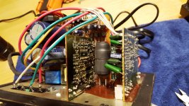
Looking at the LF amp board, everything looks to be soldered and no overheating.
Thanks again!
I don't even know any good jokes any more to offer something in return. Too Dangerous!
Looking for ideas on where might be suspect for a low output volume with the pot turned very high. (same pot controls the satellite speakers, Mids and Highs, that are quite LOUD as turned up)
Looking at the LF amp board, everything looks to be soldered and no overheating.
Thanks again!
I'm assuming you're talking about the class D sub amp.
You could check the power supply and make sure you have what it shows in the schematic. Also, you could check the mosfets for shorts from drain to source.
That's a starting place.
The rest of the class d circuit would be more difficult to troubleshoot. A scope may help there. He described the basics of all class D amps. You can buy a class d board cheap on ebay if you wanted to fix it without too much hair pulling.
These promedia 2.1 systems were $80 this past black Friday. Cheaper to replace (though wasteful and not as much of an adventure).
Last edited:
Thank you Mr Funk!
I wasn't sure if this was a Class D. But it makes sense.
When I got zero DC volts at the amp output to the woofer, I was under the impression that meant the Mosfets were working properly.
Let me go learn with the suggestions you made!
I really do appreciate the guidance. Incrementally helps as well!
I'll Be Back!
Hi jw,
Not an unreasonable request to ask for pictures. So I went in to do that.
Especially on the LF PCB amp board.
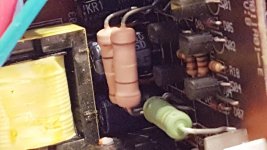
Lo and behold.... I remove a bracket holding the main PS board and I have access and can see clearly that 2 resistors are loose. (see below)
But on closer inspection, I see that it wasn't a bad or cold solder, but rather the pads have lifted. DAMN! I have access to easily resolder a cold solder. But repairing pads and or traces requires a more complex break down. (disassembly, including the Mosfets from heat sinks and most likely desoldering boards apart.)
So close, but NOT. More like so far! LOL
At least I found out what was wrong (tanish resistors loose). Now time for an expanding of my capabilities! Any tips might just help save the day! Or another frustrating experience! LOL
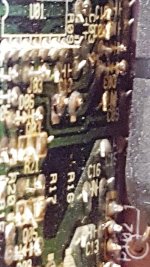
Pictures below! You can see the lifted Pads above the R16 & R17 Print!
Thanks for the request. It took me right to the problem!
Not an unreasonable request to ask for pictures. So I went in to do that.
Especially on the LF PCB amp board.
Lo and behold.... I remove a bracket holding the main PS board and I have access and can see clearly that 2 resistors are loose. (see below)
But on closer inspection, I see that it wasn't a bad or cold solder, but rather the pads have lifted. DAMN! I have access to easily resolder a cold solder. But repairing pads and or traces requires a more complex break down. (disassembly, including the Mosfets from heat sinks and most likely desoldering boards apart.)
So close, but NOT. More like so far! LOL
At least I found out what was wrong (tanish resistors loose). Now time for an expanding of my capabilities! Any tips might just help save the day! Or another frustrating experience! LOL
Pictures below! You can see the lifted Pads above the R16 & R17 Print!
Thanks for the request. It took me right to the problem!
Attachments
i bought promedia 4.1 in 2007, served me well around 2 years then switching supply blown and send it to a repair guy but after a few month he gave up. then i took it to the distributor store and charged me around $40. they replace the module not repaired it.
not long after 1year it blew up and i went to distributor again, not long until it blew up again. i was pissed badly and it ended on my garbage bin because foam was also started to crumble. but it still keep the satellite for my testing speaker during my amplifier build.
I also still have a fully functioning AltecLansing 621 in my bedroom for background music, it does not have any issue at all and even if something wrong happened, i can handle it due to it's using CHipAmp board which can be fixed easily
you can replace the amplifier board with 2.1 chipamp kit, but building a more proper subwoofer with 8" up to 12" will give you much better result
So the link at the bottom of the OP says the sub part is a Class D amp.
Three of the four pads of the two tan resistors (copper trace area around the hole for each component) pulled off the PCB from heat I guess. If they were intact, they could be resoldered in 20 seconds.
Now a disassembly to get that board isolated so I can strip that green coating on the nearest leads and solder jumper wires or, maybe replace the pads if there's some kind of kit and video on how to get it right the first time doing it? Hopefully, you guys can recommend some good resources!
It doesn't look like Klipsch sells a replacement board I could swap. with a few solder joints and heat sink paste.
I'd love to keep this old 2.1 running. The newer ones aren't as good sounding from what I've read in many posts. And if it wasn't for these pads lifting and a refoam, it's performed really well for 17 years. Works perfect for my PC for videos and also when using a software package that slows music down, but keeps pitch the same for learning guitar solos. Does a great job on that!
I am really hoping for some videos and a supplier to buy a pad replacement kit so I can be like you guys! Or at least, somewhat effective.
YUP! I'm a Dinosaur! LOL
Thanks Gentlemen!
I found a decent, straight forward link on how to replace component solder pads that have pulled off.
I'm going to buy copper tape with conductive adhesive to make the replacement pads and follow the instructions.
What I'm thinking is..... would it be better to use a high temp epoxy to attach the pads to the PCB so when the component (resistor) gets soldered in, it remains solid?
Anybody know of a high temp epoxy effective for exactly this?
Thanks!
How to Repair Damaged Printed Circuit Board Pads : 9 Steps - Instructables
You can form a loop of solid copper wire around the lead of the resistor. Solder and glue.
Use two resistors with double Resistance in parallel.
Bend the wire under the PCB to hold it in place and solder it. Apply glue on the top side.
This hopefully will reduce the heat.
You can form a loop of solid copper wire around the lead of the resistor. Solder and glue.
Use two resistors with double Resistance in parallel.
Bend the wire under the PCB to hold it in place and solder it. Apply glue on the top side.
This hopefully will reduce the heat.
So the two resistors are 1K each. One for R16 and one for R17. Mine might be the early version where they used 1 watt resistors. The latest Schematic now spec's 2 watts each. Might that have caused the heat to lift the pads? The two resistors in there are 0.625 inches or 15.9 mm in Portugal. I doubt they are 2 watts. Aren't most 2 watts bigger? So if I was to put 2 watt resistors in, would that handle the heat better, or would two, 2K Ohm, 2 watts in parallel be the best cure for heat? Metal film or Carbon? The spacing for the resistor holes is 0.8125 inches or 20.6 mm in Portugal. (on my visit list for the food and wine, people too).
So MAACO, I appreciate you addressing the inherent weakness on the front side. I'm with you on enhancing it so I get many more years since I'm in there already!
Thanks for the help Gentlemen! Seems replacing the solder pads is more complicated and not necessarily a better solution. Hot glue, top and bottom and soldering to exposed traces could get this done and done well!
Damned Perfectionist trait always makes me get into trouble!

Thank you for the experienced additional clarity!!!! Very much appreciated!
Just so I don't get any additional problems, I think I'm going to use two 2K Ohm 1 watt resistors in parallel in place of one 1K Ohm 1 watt resistor to minimize heat via divergent paths.
I found these and hopefully, they will fit the bill.... and I can match them out of 100! https://www.amazon.com/EDGELEC-Resi...2k+resistor+1+watt&qid=1614317044&sr=8-2&th=1
Thanks again! Wish me luck! LOL
All other things being equal, the amount of heat generated will not change. Its dispersion will improve slightly. The tracks could be damaged by vibration, not just heat. Fasten and cushion heavy parts.
I think I'm going to use two 2K Ohm 1 watt resistors in parallel in place of one 1K Ohm 1 watt resistor
Put them in and test. Can you touch them ? No ? increase Wattage or put three of them, or find the fault what's heating them up.
You can also put resistors in series like in many vintage amps. Say 500+500.
The advantage of putting them in parallel is if one fails, resistance will double and hopefully will reduce current to the circuit.
I have done this parallel mod on a PA system which derived the pre-amp rails from the main amp rails and the leg pads were beginning to melt.
- Status
- This old topic is closed. If you want to reopen this topic, contact a moderator using the "Report Post" button.
- Home
- Amplifiers
- Solid State
- Subwoofer Amp Help Needed! Original ProMedia 2.1