Choosing of best sounding OP AMPs for the lowest possible THD+N - really the best Approach ??
First some extracts from the rubric "Integrated Opamps and their Properties" (From page 109-165 in the book "Small Signal Audio Design" - go to
Facebook
from Mr. DOUGLAS SELF)
Introduction:
Audio design has for many years relied on a very small number of integrated opamp types; the TL072
and the 5532 dominated the audio small-signal scene for many years.
The TL072, with its JFET inputs, was used wherever its negligible input bias currents and low cost were
important. For a long time the 5534/5532 was much more expensive than the TL072, so the
latter was used wherever feasible in an audio system, despite its inferior noise, distortion, and
load-driving capabilities. The 5534 (predecessor TDA1034 - go to
TDA1034NB datasheet)
was reserved for critical parts of the circuitry. Although it
took many years, the price of the 5534 is now down to the point where you need a very good
reason to choose any other type of opamp for audio work.
The TL072 and the 5532 are dual opamps; the single equivalents are TL071 and 5534. Dual
opamps are used almost universally, as the package containing two is usually cheaper than
the package containing one, simply because it is more popular.
There are however other opamps, some of which can be useful, and a selected range is
covered here.
Opamp Properties: distortion
Relatively few discussions of opamp behaviour deal with non-linear distortion, perhaps
because it is a complex business. Opamp ‘accuracy’ is closely related, but the term is often
applied only to DC operation. Accuracy here is often specified in terms of bits, so ‘20-bit
accuracy’ means errors not exceeding one part in 2 to the 20, which is -120 dB or 0.0001%.
Audio signal distortion is of course a dynamic phenomenon, very sensitive to frequency, and
DC specs are of no use at all in estimating it.
Distortion is always expressed as a ratio, and can be quoted as a percentage, as number of
decibels, or in parts per million. With the rise of digital processing, treating distortion as the
quantization error arising from the use of a given number of bits has become more popular.
Figure 4.2 hopefully provides a way of keeping perspective when dealing with these different
metrics.
There are several different causes of distortion in opamps. We will now examine them.
Opamp internal distortion:
This is what might be called the basic distortion produced by the opamp you have selected.
Even if you scrupulously avoid clipping, slew-limiting, and common-mode issues, opamps
are not distortion free, though some types such as the 5532 and the LM4562 have very
low levels.
If distortion appears when the opamp is run with shunt feedback, to prevent
common-mode voltages on the inputs, and with very light output loading, then it is probably
wholly internal and there is nothing to be done about it except pick a better opamp.
If the distortion is higher than expected, the cause may be internal instability provoked by
putting a capacitative load directly on the output, or neglecting the supply decoupling. The
classic example of the latter effect is the 5532, which shows high distortion if there is not a
capacitor across the supply rails close to the package; 100 nF is usually adequate. No actual
HF oscillation is visible on the output with a general-purpose oscilloscope, so the problem
may be instability in one of the intermediate gain stages.
Slew rate limiting distortion
While this is essentially an overload condition, it is wholly the designer's responsibility. If
users whack up the gain until the signal is within a hair of clipping, they should still be able
to assume that slew-limiting will never occur, even with aggressive material full of high
frequencies.
Arranging this is not too much of a problem. If the rails are set at the usual maximum
voltage, i.e. ±18 V, then the maximum possible signal amplitude is 12.7 Vrms, ignoring the
saturation voltages of the output stage. To reproduce this level cleanly at 20 kHz requires a
minimum slew rate of only 2.3 V/μs. Most opamps can do much better than this, though with
the OP27 (2.8 V/μs) you are sailing rather close to the wind. The old LM741 looks as though
it would be quite unusable, as its very limited 0.5 V/μs slew rate allows a full output swing
only up to 4.4 kHz.
Horrific as it may now appear, audio paths full of LM741s were quite common in the early
1970s. Entire mixers were built with no other active devices, and what complaints there were
tended to be about noise rather than distortion. The reason for this is that full-level signals at
20 kHz simply do not occur in reality; the energy at the HF end of the audio spectrum is wellknown to be much lower than that at the bass end.
This assumes that slew-limiting has an abrupt onset as level increases, rather like clipping.
This is in general the case. As the input frequency rises and an opamp gets closer to slewlimiting, the input stage is working harder to supply the demands of the compensation
capacitance. There is an absolute limit to the amount of current this stage can supply, and
when you hit it the distortion shoots up, much as it does when you hit the supply rails and
induce voltage clipping. Before you reach this point, the linearity may be degraded, but
usually only slightly until you get close to the limit. It is not normally necessary to keep
big margins of safety when dealing with slew-limiting. If you are employing the Usual
Suspects in the audio opamp world – the TL072, the 5532 and the LM4562, with maximal
slew rates of 13, 9 and 20 V/μs respectively, you are most unlikely to suffer any slew rate
non-linearity.
Selecting the right opamp
Until recently, the 5532 was pre-eminent. It is found in almost every mixing console, and in a
large number of preamplifiers. Distortion is very low, even when driving 600 Ω loads. Noise
is very low, and the balance of voltage and current noise in the input stage is well–matched
to moving-magnet phono cartridges; in many applications discrete devices give no significant
advantage. Large-quantity production has brought the price down to a point where a powerful
reason is required to pick any other device.
The 5532 is not, however, perfect. It suffers common-mode distortion. It has high bias and offset
currents at the inputs, as an inevitable result of using a bipolar input stage (for low noise) without
any sort of bias-cancellation circuitry. The 5532 is not in the forefront for DC accuracy, though
it's not actually that bad. The offset voltage spec is 0.5 mV typical, 4 mV max, compared with
3 mV typical, 6 mV max for the popular TL072. I have actually used 5532s to replace TL072s
when offset voltage was a problem, but the increased bias current was acceptable.
With horrible inevitability, the very popularity and excellent technical performance of the
5532 has led to it being criticised by subjectivists who have contrived to convince themselves
that they can tell opamps apart by listening to music played through them. This always makes
me laugh, because there is probably no music on the planet that has not passed through a
hundred or more 5532s on its way to the consumer.
The LM4562 represents a real advance on the 5532. It is however still a good deal more
expensive, and is not perfect – it appears to be more easily damaged by excess commonmode voltages, and there is some evidence it is more susceptible to RF demodulation.
In some applications, such as low-cost mixing consoles, bipolar-style bias currents are a
real nuisance because keeping them out of EQ pots to prevent scratching noises requires an
inappropriate number of blocking capacitors. There are plenty of JFET input opamps around
with negligible bias currents, but there is no obviously superior device that is the equivalent
of the 5532. The TL072 has been used in this application for many years but its HF linearity
is not first-class and distortion across the band deteriorates badly as output loading increases.
However, the opamps in many EQ sections work in the shunt-feedback configuration with
no CM voltage on the inputs, and this reduces the distortion considerably. When low bias
currents are needed with superior performance then the OPA2134 is often a good choice,
though it is at least four times as expensive as the TL072.
Opamps surveyed: BJT input types
The rest of this chapter looks at some opamp types and examines their performance, with the
5532 the usual basis for comparison. The parts shown here are not necessarily intended as
audio opamps, though some, such as the OP275 and the OPA2134, were specifically designed
as such. They have however all seen use, in varying numbers, in audio applications. Bipolar input opamps are dealt with first.
The LM741 opamp
The LM741 is only included here for its historical interest; in its day it was a most significant development, and to my mind, the first really practical opamp. It was introduced by Fairchild in 1968 and is considered a second-generation opamp, the 709 being first generation. The LM741 had (and indeed has) effective short-circuit protection and internal compensation for stability at unity gain, and was much easier to make work in a real circuit than its predecessors. It was clear that it was noisy compared with discrete circuitry, and you sometimes had to keep the output level down if slew-limiting was to be avoided, but with care it was usable in audio. Probably the last place the LM741 lingered was in the integrators of state-variable EQ filters, where neither indifferent noise performance nor poor slewing capability is a serious problem; see Chapter 15 for more details on this application. The LM741 is a single opamp. The dual version is the LM747. Figure 4.19 shows a region between 100 Hz and 4 kHz where distortion rises at 6 dB/octave. This is the result of the usual dominant-pole Miller compensation scheme. When slew limiting begins, the slope increases and THD rises rapidly with frequency.
The NE5532/5534 opamp
The 5532 is a low-noise, low distortion bipolar dual opamp, with internal compensation for unity-gain stability. The 5534 is a single version internally compensated for gains down to three times, and an external compensation capacitor can be added for unity-gain stability; 22 pF is the usual value. The 5532 achieves unity-gain stability by having degeneration resistors in the emitter circuits of the input transistors, to reduce the open-loop gain, and this is why it is noisier than the 5534. The common-mode range of the inputs is a healthy ±13V, with no phase inversion problems if this is exceeded. It has a distinctly higher power consumption than the TL072, drawing approx 4 mA per opamp section when quiescent. The DIL version runs perceptibly warm when quiescent on ±17 V rails. The 5534/5532 has bipolar transistor input devices. This means it gives low noise with low source resistances, but draws a relatively high bias current through the input pins. The input devices are NPN, so the bias currents flow into the chip from the positive rail. If an input is fed through a significant resistance then the input pin will be more negative than ground due to the voltage-drop caused by the bias current. The inputs are connected together with back-to-back diodes for reverse-voltage protection; and should not be forcibly pulled to different voltages. The 5532 is intended for linear operation, and using it as a comparator is not recommended.
As can be seen from Figure 4.20 , the 5532 is almost distortion-free, even when driving the maximum 500 Ohm load. The internal circuitry of the 5532 has never been officially explained, but appears to consist of nested Miller loops that permit high levels of internal negative feedback. The 5532 is the dual of the 5534, and is much more commonly used than the single as it is cheaper per opamp and does not require an external compensation capacitor when used at unity gain. The 5532/5534 is made by several companies, but they are not all created equal. Those by Fairchild, JRC, and ON-Semi have significantly lower THD at 20 kHz and above, and we’re talking about a factor of two or three here. The 5532 and 5534 type opamps require adequate supply-decoupling if they are to remain stable; otherwise they appear to be subject to some sort of internal oscillation that degrades linearity without being visible on a normal oscilloscope. The essential requirement is that the +ve and -ve rails should be decoupled with a 100 nF capacitor between them, at a distance of not more than a few millimetres from the opamp; normally one such capacitor is fitted per package as close to it as possible. It is not necessary, and often not desirable to have two capacitors going to ground; every capacitor between a supply rail and ground carries the risk of injecting rail noise into the ground.
The LM4562 opamp
The LM4562 is a new opamp, which first became freely available at the beginning of 2007. It is a National Semiconductor product. It is a dual opamp – there is no single or quad version. It costs about ten times as much as a 5532. The input noise voltage is typically 2.7nV/√ Hz, which is substantially lower than the 4nV/√ Hz of the 5532. For suitable applications with low source impedances this translates into a useful noise advantage of 3.4 dB. The bias current is typically 10 nA, which is very low and would normally imply that bias-cancellation, with its attendant noise problems, was being used. However, in my testing I have seen no sign of excess noise, and the data sheet is silent on the subject. No details of the internal circuitry have been released so far, and quite probably never will be. It is not fussy about decoupling, and as with the 5532, 100 nF across the supply rails close to the package should ensure HF stability. The slew rate is typically ±20 V/μs, more than twice as quick as the 5532. The first THD plot in Figure 4.22 shows the LM4562 working at a closed-loop gain of 2.2 times in shunt feedback mode, at a high level of 10 Vrms. The top of the THD scale is 0.001%, something you will see with no other opamp in this survey. The no-load trace is barely distinguishable from the AP SYS-2702 output, and even with a heavy 500 Ω load driven at 10 Vrms there is only a very small amount of extra THD, reaching 0.0007% at 20 kHz. Figure 4.23 shows the LM4562 working at a gain of 3.2 times in series feedback mode, both modes having a noise gain of 3.2 times. There is little extra distortion from 500 Ω.
For Figures 4.22 and 4.23 the feedback resistances were 2k2 and 1 kΩ, so the minimum source resistance presented to the inverting input is 687 Ω. In Figure 4.24 extra source resistances were then put in series with the input path, (as was done with the 5532 in the section above on common-mode distortion) and this revealed a remarkable property of the LM4562 – it is much more resistant to common-mode distortion than the 5532. At 10 Vrms and 10 kHz, with a 10 kΩ source resistance the 5532 generates 0.0014% THD (see Figure 4.6 ) but the LM4562 gives only 0.00046% under the same conditions. I strongly suspect that the LM4562 has a more sophisticated input stage than the 5532, probably incorporating cascoding to minimise the effects of common-mode voltages. Note that only the rising curves to the right represent actual distortion. The raised levels of the horizontal traces at the LF end is due to Johnson noise from the extra series resistance. It has taken an unbelievably long time – nearly 30 years – for a better audio opamp than the 5532 to come along, but at last it has happened. The LM4562 is superior in just about every parameter, but it has much higher current noise. At present it also has a much higher price, but hopefully that will change.
The AD797 opamp
The AD797 (Analog Devices) is a single opamp with very low voltage noise and distortion. It appears to have been developed primarily for the cost-no-object application of submarine sonar, but it works very effectively with normal audio – if you can afford to use it. The cost is something like 20 times that of a 5532. No dual version is available, so the cost ratio per opamp section is forty times. This is a remarkably quiet device in terms of voltage noise, but current noise is correspondingly high due to the high currents in the input devices. Early versions appeared to be rather difficult to stabilise at HF, but the current product is no harder to apply than the 5532. Possibly there has been a design tweak, or on the other hand my impression may be wholly mistaken. The AD797 incorporates an ingenious feature for internal distortion cancellation. This is described on the manufacturer’s data sheet. Figure 4.25 shows that it works effectively.
The OP27 opamp
The OP27 from Analog Devices is a bipolar input, single opamp primarily designed for low noise and DC precision. It was not intended for audio use, but in spite of this it is frequently recommended for such applications as RIAA and tape head preamps. This is unfortunate, because while at first sight it appears that the OP27 is quieter than the 5534/5532, as the e n is 3.2nV/√ Hz compared with 4nV/√ Hz for the 5534, in practice it is usually slightly noisier. This is because the OP27 is in fact optimised for DC characteristics, and so has input bias-current cancellation circuitry that generates common-mode noise. When the impedances on the two inputs are very different – which is the case in RIAA preamps – the CM noise does not cancel, and this appears to degrade the overall noise performance significantly. For a bipolar input opamp, there appears to be a high level of common-mode input distortion, enough to bury the output distortion caused by loading; see Figures 4.26 and 4.27 . It is likely that this too is related to the bias-cancellation circuitry, as it does not occur in the 5532. The maximum slew rate is low compared with other opamps, being typically 2.8 V/μs. However, this is not the problem it may appear. This slew rate would allow a maximum amplitude at 20 kHz of 16 Vrms, if the supply rails permitted it. I have never encountered any particular difficulties with decoupling or stability of the OP27.
The OP275 opamp
The Analog Devices OP275 is one of the few opamps specifically marketed as an audio device. Its most interesting characteristic is the Butler input stage which combines bipolar and JFET devices. The idea is that the bipolars give accuracy and low noise, while the JFETs give speed and ‘the sound quality of JFETs’. That final phrase is not a happy thing to see on a datasheet from a major manufacturer; the sound of JFETs (if any) would be the sound of high distortion. Just give us the facts, please. The OP275 is a dual opamp; no single version is available. It is quite expensive, about six times the price of a 5532, and its performance in most respects is inferior. It is noisier, has higher distortion, and does not like heavy loads (see Figures 4.30 and 4.31 ). The CM range is only about two-thirds of the voltage between the supply rails, and I bias is high due to the BJT part of the input stage. Unless you think there is something magical about the BJT/JFET input stage – and I am quite sure there is not – it is probably best avoided.
The THD at 10 kHz with a 600 Ω load is 0.0025% for shunt and 0.009% for series feedback; there is significant CM distortion in the input stage, which is almost certainly coming from the JFETs (I appreciate the output levels are not the same but I think this only accounts for a small part of the THD difference). Far from adding magical properties to the input stage, the JFETs seem to be just making it worse.
Opamps surveyed: JFET input types
Opamps with JFET inputs tend to have higher voltage noise and lower current noise than BJT input types, and therefore give a better noise performance with high source resistances. Their very low bias currents often allow circuitry to be simplified.
The TL072 opamp
The TL072 is one of the most popular opamps, having very high-impedance inputs, with effectively zero bias and offset currents. The JFET input devices give their best noise performance at medium impedances, in the range 1 kΩ–10 kΩ. It has a modest power consumption at typically 1.4 mA per opamp section, which is significantly less than the 5532. The slew rate is higher than for the 5532, at 13 V/μs against 9 V/μs. The TL072 is a dual opamp. There is a single version called the TL071 which has offset null pins. However, the TL072 is not THD free in the way the 5532 is. In audio usage, distortion depends primarily upon how heavily the output is loaded. The maximum loading is a trade-off between quality and circuit economy, and I would put 2 kΩ as the lower limit. This opamp is not the first choice for audio use unless the near-zero bias currents (which allow circuit economies by making blocking capacitors unnecessary), the low price, or the modest power consumption are dominant factors. It is a quirk of this device that the input common-mode range does not extend all the way between the rails. If the common mode voltage gets to within a couple of volts of the V– rail, the opamp suffers phase reversal and the inputs swap their polarities. There may be really horrible clipping, where the output hits the bottom rail and then shoots up to hit the top one, or the stage may simply latch up until the power is turned off. TL072s are relatively relaxed about supply rail decoupling, though they will sometimes show very visible oscillation if they are at the end of long thin supply tracks. One or two rail-to-rail decoupling capacitors (e.g. 100 nF) per few centimetres is usually sufficient to deal with this, but normal practice is to not take chances, and allow one capacitor per package as with other opamps. Because of common-mode distortion, a TL072 in shunt configuration is always more linear. In particular compare the results for 3k3 load in Figures 4.32 and 4.33. At heavier loadings the difference is barely visible because most of the distortion is coming from the output stage. TL072/71 opamps are prone to HF oscillation if faced with significant capacitance to ground on the output pin; this is particularly likely when they are used as unity-gain buffers with 100% feedback. A few inches of track can sometimes be enough. This can be cured by an isolating resistor, in the 47 to 75 Ω range, in series with the output, placed at the opamp end of the track.
The OPA2134 opamp
The OPA2134 is a Burr-Brown product, the dual version of the OPA134. The manufacturer claims it has superior sound quality, due to its JFET input stage. Regrettably, but not surprisingly, no evidence is given to back up this assertion. The input noise voltage is 8nV/√ Hz, almost twice that of the 5532. The slew rate is typically ±20 V/μs, which is ample. It does not appear to be optimised for DC precision, the typical offset voltage being ±1 mV, but this is usually good enough for audio work. I have used it many times as a DC servo in power amplifiers, the low bias currents allowing high resistor values and correspondingly small capacitors. The OPA2134 does not show phase-reversal anywhere in the common-mode range, which immediately marks it as superior to the TL072. The two THD plots in Figures 4.36 and 4.37 show the device working at a gain of three times in both shunt and series feedback modes. It is obvious that a problem emerges in the series plot, where the THD is higher by about three times at 5 Vrms and 10 kHz. This distortion increases with level, which immediately suggests common-mode distortion in the input stage. Distortion increases with even moderate loading; see Figure 4.38 .
This is a relatively modern and sophisticated opamp. When you need JFET inputs (usually because significant input bias currents would be a problem) this definitely beats the TL072; it is, however, four to five times more expensive.
The OPA604 opamp
The OPA604 from Burr-Brown is a single JFET-input opamp which has been specially designed to give low distortion. The simplified internal circuit diagram in the data sheet includes an enigmatic box intriguingly labelled ‘Distortion Rejection Circuitry’. This apparently ‘linearizes the open-loop response and increases voltage gain’ but no details as to how are given; whatever is in there appears to have been patented so it ought to be possible to track it down. However, despite this, the distortion is not very low even with no load, (see Figure 4.39 ) and is markedly inferior to the 5532. The OPA604 is not optimised for DC precision, the typical offset voltage being ±1 mV. The OPA2604 is the dual version, which omits the offset null pins. The data sheet includes a discussion that attempts to show that JFET inputs produce a more pleasant type of distortion than BJT inputs. This unaccountably omits the fact that the much higher transconductance of BJTs means that they can be linearised by emitter degeneration so that they produce far less distortion of whatever type than a JFET input [7]. Given that the OPA604 costs five times as much as a 5532, it is not very clear under what circumstances this opamp would be a good choice.
The OPA627 opamp
The OPA627 from Burr-Brown is a laser-trimmed JFET input opamp with excellent DC precision; the input offset voltage being typically ±100 μV. The distortion is very low, even into a 600 Ω load, though it is increased by the usual common-mode distortion when series feedback is used. The OP627 is a single opamp and no dual version is available. The OPA637 is a decompensated version only stable for closed-loop gains of five or more. This opamp makes a brilliant DC servo for power amplifiers, if you can afford it; it costs about 50 times as much as a 5532, which is 100 times more per opamp section, and about 20 times more per opamp than the OPA2134, which is my usual choice for DC servo work. The current noise i n is very low, the lowest of any opamp examined in this book, apparently due to the use of Difet (dielectrically isolated JFET) input devices, and so it will give a good noise performance with high source resistances. Voltage noise is also very respectable at 5.2 nV/√ Hz, only fractionally more than the 5532. The series feedback case barely has more distortion than the shunt one, and only at the extreme HF end. It appears that the Difet input technology also works well to prevent input non-linearity and CM distortion. See Figures 4.40 and 4.41.
My asked questions are to find in post #2
Interesting URL's in this case:
Survival Between Microphone and Voice Coil from Bruno Putzeys
go to page 9, post #84 under
https://www.diyaudio.com/forums/sol...ooks-overview-google-books-9.html#post6739509
and
https://www.analog.com/media/en/training-seminars/design-handbooks/Op-Amp-Applications/SectionH.pdf
https://convexoptimization.com/TOOLS/groner.pdf
Profusion Audio Semiconductors - Audio Op-amp Guide | Profusion
https://www.nanovolt.ch/resources/ic_opamps/pdf/opamp_distortion.pdf
ESP SIM (Sound Impairment Monitor)
First some extracts from the rubric "Integrated Opamps and their Properties" (From page 109-165 in the book "Small Signal Audio Design" - go to
from Mr. DOUGLAS SELF)
Introduction:
Audio design has for many years relied on a very small number of integrated opamp types; the TL072
and the 5532 dominated the audio small-signal scene for many years.
The TL072, with its JFET inputs, was used wherever its negligible input bias currents and low cost were
important. For a long time the 5534/5532 was much more expensive than the TL072, so the
latter was used wherever feasible in an audio system, despite its inferior noise, distortion, and
load-driving capabilities. The 5534 (predecessor TDA1034 - go to
TDA1034NB datasheet)
was reserved for critical parts of the circuitry. Although it
took many years, the price of the 5534 is now down to the point where you need a very good
reason to choose any other type of opamp for audio work.
The TL072 and the 5532 are dual opamps; the single equivalents are TL071 and 5534. Dual
opamps are used almost universally, as the package containing two is usually cheaper than
the package containing one, simply because it is more popular.
There are however other opamps, some of which can be useful, and a selected range is
covered here.
Opamp Properties: distortion
Relatively few discussions of opamp behaviour deal with non-linear distortion, perhaps
because it is a complex business. Opamp ‘accuracy’ is closely related, but the term is often
applied only to DC operation. Accuracy here is often specified in terms of bits, so ‘20-bit
accuracy’ means errors not exceeding one part in 2 to the 20, which is -120 dB or 0.0001%.
Audio signal distortion is of course a dynamic phenomenon, very sensitive to frequency, and
DC specs are of no use at all in estimating it.
Distortion is always expressed as a ratio, and can be quoted as a percentage, as number of
decibels, or in parts per million. With the rise of digital processing, treating distortion as the
quantization error arising from the use of a given number of bits has become more popular.
Figure 4.2 hopefully provides a way of keeping perspective when dealing with these different
metrics.
There are several different causes of distortion in opamps. We will now examine them.
Opamp internal distortion:
This is what might be called the basic distortion produced by the opamp you have selected.
Even if you scrupulously avoid clipping, slew-limiting, and common-mode issues, opamps
are not distortion free, though some types such as the 5532 and the LM4562 have very
low levels.
If distortion appears when the opamp is run with shunt feedback, to prevent
common-mode voltages on the inputs, and with very light output loading, then it is probably
wholly internal and there is nothing to be done about it except pick a better opamp.
If the distortion is higher than expected, the cause may be internal instability provoked by
putting a capacitative load directly on the output, or neglecting the supply decoupling. The
classic example of the latter effect is the 5532, which shows high distortion if there is not a
capacitor across the supply rails close to the package; 100 nF is usually adequate. No actual
HF oscillation is visible on the output with a general-purpose oscilloscope, so the problem
may be instability in one of the intermediate gain stages.
Slew rate limiting distortion
While this is essentially an overload condition, it is wholly the designer's responsibility. If
users whack up the gain until the signal is within a hair of clipping, they should still be able
to assume that slew-limiting will never occur, even with aggressive material full of high
frequencies.
Arranging this is not too much of a problem. If the rails are set at the usual maximum
voltage, i.e. ±18 V, then the maximum possible signal amplitude is 12.7 Vrms, ignoring the
saturation voltages of the output stage. To reproduce this level cleanly at 20 kHz requires a
minimum slew rate of only 2.3 V/μs. Most opamps can do much better than this, though with
the OP27 (2.8 V/μs) you are sailing rather close to the wind. The old LM741 looks as though
it would be quite unusable, as its very limited 0.5 V/μs slew rate allows a full output swing
only up to 4.4 kHz.
Horrific as it may now appear, audio paths full of LM741s were quite common in the early
1970s. Entire mixers were built with no other active devices, and what complaints there were
tended to be about noise rather than distortion. The reason for this is that full-level signals at
20 kHz simply do not occur in reality; the energy at the HF end of the audio spectrum is wellknown to be much lower than that at the bass end.
This assumes that slew-limiting has an abrupt onset as level increases, rather like clipping.
This is in general the case. As the input frequency rises and an opamp gets closer to slewlimiting, the input stage is working harder to supply the demands of the compensation
capacitance. There is an absolute limit to the amount of current this stage can supply, and
when you hit it the distortion shoots up, much as it does when you hit the supply rails and
induce voltage clipping. Before you reach this point, the linearity may be degraded, but
usually only slightly until you get close to the limit. It is not normally necessary to keep
big margins of safety when dealing with slew-limiting. If you are employing the Usual
Suspects in the audio opamp world – the TL072, the 5532 and the LM4562, with maximal
slew rates of 13, 9 and 20 V/μs respectively, you are most unlikely to suffer any slew rate
non-linearity.
Selecting the right opamp
Until recently, the 5532 was pre-eminent. It is found in almost every mixing console, and in a
large number of preamplifiers. Distortion is very low, even when driving 600 Ω loads. Noise
is very low, and the balance of voltage and current noise in the input stage is well–matched
to moving-magnet phono cartridges; in many applications discrete devices give no significant
advantage. Large-quantity production has brought the price down to a point where a powerful
reason is required to pick any other device.
The 5532 is not, however, perfect. It suffers common-mode distortion. It has high bias and offset
currents at the inputs, as an inevitable result of using a bipolar input stage (for low noise) without
any sort of bias-cancellation circuitry. The 5532 is not in the forefront for DC accuracy, though
it's not actually that bad. The offset voltage spec is 0.5 mV typical, 4 mV max, compared with
3 mV typical, 6 mV max for the popular TL072. I have actually used 5532s to replace TL072s
when offset voltage was a problem, but the increased bias current was acceptable.
With horrible inevitability, the very popularity and excellent technical performance of the
5532 has led to it being criticised by subjectivists who have contrived to convince themselves
that they can tell opamps apart by listening to music played through them. This always makes
me laugh, because there is probably no music on the planet that has not passed through a
hundred or more 5532s on its way to the consumer.
The LM4562 represents a real advance on the 5532. It is however still a good deal more
expensive, and is not perfect – it appears to be more easily damaged by excess commonmode voltages, and there is some evidence it is more susceptible to RF demodulation.
In some applications, such as low-cost mixing consoles, bipolar-style bias currents are a
real nuisance because keeping them out of EQ pots to prevent scratching noises requires an
inappropriate number of blocking capacitors. There are plenty of JFET input opamps around
with negligible bias currents, but there is no obviously superior device that is the equivalent
of the 5532. The TL072 has been used in this application for many years but its HF linearity
is not first-class and distortion across the band deteriorates badly as output loading increases.
However, the opamps in many EQ sections work in the shunt-feedback configuration with
no CM voltage on the inputs, and this reduces the distortion considerably. When low bias
currents are needed with superior performance then the OPA2134 is often a good choice,
though it is at least four times as expensive as the TL072.
Opamps surveyed: BJT input types
The rest of this chapter looks at some opamp types and examines their performance, with the
5532 the usual basis for comparison. The parts shown here are not necessarily intended as
audio opamps, though some, such as the OP275 and the OPA2134, were specifically designed
as such. They have however all seen use, in varying numbers, in audio applications. Bipolar input opamps are dealt with first.
The LM741 opamp
The LM741 is only included here for its historical interest; in its day it was a most significant development, and to my mind, the first really practical opamp. It was introduced by Fairchild in 1968 and is considered a second-generation opamp, the 709 being first generation. The LM741 had (and indeed has) effective short-circuit protection and internal compensation for stability at unity gain, and was much easier to make work in a real circuit than its predecessors. It was clear that it was noisy compared with discrete circuitry, and you sometimes had to keep the output level down if slew-limiting was to be avoided, but with care it was usable in audio. Probably the last place the LM741 lingered was in the integrators of state-variable EQ filters, where neither indifferent noise performance nor poor slewing capability is a serious problem; see Chapter 15 for more details on this application. The LM741 is a single opamp. The dual version is the LM747. Figure 4.19 shows a region between 100 Hz and 4 kHz where distortion rises at 6 dB/octave. This is the result of the usual dominant-pole Miller compensation scheme. When slew limiting begins, the slope increases and THD rises rapidly with frequency.
The NE5532/5534 opamp
The 5532 is a low-noise, low distortion bipolar dual opamp, with internal compensation for unity-gain stability. The 5534 is a single version internally compensated for gains down to three times, and an external compensation capacitor can be added for unity-gain stability; 22 pF is the usual value. The 5532 achieves unity-gain stability by having degeneration resistors in the emitter circuits of the input transistors, to reduce the open-loop gain, and this is why it is noisier than the 5534. The common-mode range of the inputs is a healthy ±13V, with no phase inversion problems if this is exceeded. It has a distinctly higher power consumption than the TL072, drawing approx 4 mA per opamp section when quiescent. The DIL version runs perceptibly warm when quiescent on ±17 V rails. The 5534/5532 has bipolar transistor input devices. This means it gives low noise with low source resistances, but draws a relatively high bias current through the input pins. The input devices are NPN, so the bias currents flow into the chip from the positive rail. If an input is fed through a significant resistance then the input pin will be more negative than ground due to the voltage-drop caused by the bias current. The inputs are connected together with back-to-back diodes for reverse-voltage protection; and should not be forcibly pulled to different voltages. The 5532 is intended for linear operation, and using it as a comparator is not recommended.
As can be seen from Figure 4.20 , the 5532 is almost distortion-free, even when driving the maximum 500 Ohm load. The internal circuitry of the 5532 has never been officially explained, but appears to consist of nested Miller loops that permit high levels of internal negative feedback. The 5532 is the dual of the 5534, and is much more commonly used than the single as it is cheaper per opamp and does not require an external compensation capacitor when used at unity gain. The 5532/5534 is made by several companies, but they are not all created equal. Those by Fairchild, JRC, and ON-Semi have significantly lower THD at 20 kHz and above, and we’re talking about a factor of two or three here. The 5532 and 5534 type opamps require adequate supply-decoupling if they are to remain stable; otherwise they appear to be subject to some sort of internal oscillation that degrades linearity without being visible on a normal oscilloscope. The essential requirement is that the +ve and -ve rails should be decoupled with a 100 nF capacitor between them, at a distance of not more than a few millimetres from the opamp; normally one such capacitor is fitted per package as close to it as possible. It is not necessary, and often not desirable to have two capacitors going to ground; every capacitor between a supply rail and ground carries the risk of injecting rail noise into the ground.
The LM4562 opamp
The LM4562 is a new opamp, which first became freely available at the beginning of 2007. It is a National Semiconductor product. It is a dual opamp – there is no single or quad version. It costs about ten times as much as a 5532. The input noise voltage is typically 2.7nV/√ Hz, which is substantially lower than the 4nV/√ Hz of the 5532. For suitable applications with low source impedances this translates into a useful noise advantage of 3.4 dB. The bias current is typically 10 nA, which is very low and would normally imply that bias-cancellation, with its attendant noise problems, was being used. However, in my testing I have seen no sign of excess noise, and the data sheet is silent on the subject. No details of the internal circuitry have been released so far, and quite probably never will be. It is not fussy about decoupling, and as with the 5532, 100 nF across the supply rails close to the package should ensure HF stability. The slew rate is typically ±20 V/μs, more than twice as quick as the 5532. The first THD plot in Figure 4.22 shows the LM4562 working at a closed-loop gain of 2.2 times in shunt feedback mode, at a high level of 10 Vrms. The top of the THD scale is 0.001%, something you will see with no other opamp in this survey. The no-load trace is barely distinguishable from the AP SYS-2702 output, and even with a heavy 500 Ω load driven at 10 Vrms there is only a very small amount of extra THD, reaching 0.0007% at 20 kHz. Figure 4.23 shows the LM4562 working at a gain of 3.2 times in series feedback mode, both modes having a noise gain of 3.2 times. There is little extra distortion from 500 Ω.
For Figures 4.22 and 4.23 the feedback resistances were 2k2 and 1 kΩ, so the minimum source resistance presented to the inverting input is 687 Ω. In Figure 4.24 extra source resistances were then put in series with the input path, (as was done with the 5532 in the section above on common-mode distortion) and this revealed a remarkable property of the LM4562 – it is much more resistant to common-mode distortion than the 5532. At 10 Vrms and 10 kHz, with a 10 kΩ source resistance the 5532 generates 0.0014% THD (see Figure 4.6 ) but the LM4562 gives only 0.00046% under the same conditions. I strongly suspect that the LM4562 has a more sophisticated input stage than the 5532, probably incorporating cascoding to minimise the effects of common-mode voltages. Note that only the rising curves to the right represent actual distortion. The raised levels of the horizontal traces at the LF end is due to Johnson noise from the extra series resistance. It has taken an unbelievably long time – nearly 30 years – for a better audio opamp than the 5532 to come along, but at last it has happened. The LM4562 is superior in just about every parameter, but it has much higher current noise. At present it also has a much higher price, but hopefully that will change.
The AD797 opamp
The AD797 (Analog Devices) is a single opamp with very low voltage noise and distortion. It appears to have been developed primarily for the cost-no-object application of submarine sonar, but it works very effectively with normal audio – if you can afford to use it. The cost is something like 20 times that of a 5532. No dual version is available, so the cost ratio per opamp section is forty times. This is a remarkably quiet device in terms of voltage noise, but current noise is correspondingly high due to the high currents in the input devices. Early versions appeared to be rather difficult to stabilise at HF, but the current product is no harder to apply than the 5532. Possibly there has been a design tweak, or on the other hand my impression may be wholly mistaken. The AD797 incorporates an ingenious feature for internal distortion cancellation. This is described on the manufacturer’s data sheet. Figure 4.25 shows that it works effectively.
The OP27 opamp
The OP27 from Analog Devices is a bipolar input, single opamp primarily designed for low noise and DC precision. It was not intended for audio use, but in spite of this it is frequently recommended for such applications as RIAA and tape head preamps. This is unfortunate, because while at first sight it appears that the OP27 is quieter than the 5534/5532, as the e n is 3.2nV/√ Hz compared with 4nV/√ Hz for the 5534, in practice it is usually slightly noisier. This is because the OP27 is in fact optimised for DC characteristics, and so has input bias-current cancellation circuitry that generates common-mode noise. When the impedances on the two inputs are very different – which is the case in RIAA preamps – the CM noise does not cancel, and this appears to degrade the overall noise performance significantly. For a bipolar input opamp, there appears to be a high level of common-mode input distortion, enough to bury the output distortion caused by loading; see Figures 4.26 and 4.27 . It is likely that this too is related to the bias-cancellation circuitry, as it does not occur in the 5532. The maximum slew rate is low compared with other opamps, being typically 2.8 V/μs. However, this is not the problem it may appear. This slew rate would allow a maximum amplitude at 20 kHz of 16 Vrms, if the supply rails permitted it. I have never encountered any particular difficulties with decoupling or stability of the OP27.
The OP275 opamp
The Analog Devices OP275 is one of the few opamps specifically marketed as an audio device. Its most interesting characteristic is the Butler input stage which combines bipolar and JFET devices. The idea is that the bipolars give accuracy and low noise, while the JFETs give speed and ‘the sound quality of JFETs’. That final phrase is not a happy thing to see on a datasheet from a major manufacturer; the sound of JFETs (if any) would be the sound of high distortion. Just give us the facts, please. The OP275 is a dual opamp; no single version is available. It is quite expensive, about six times the price of a 5532, and its performance in most respects is inferior. It is noisier, has higher distortion, and does not like heavy loads (see Figures 4.30 and 4.31 ). The CM range is only about two-thirds of the voltage between the supply rails, and I bias is high due to the BJT part of the input stage. Unless you think there is something magical about the BJT/JFET input stage – and I am quite sure there is not – it is probably best avoided.
The THD at 10 kHz with a 600 Ω load is 0.0025% for shunt and 0.009% for series feedback; there is significant CM distortion in the input stage, which is almost certainly coming from the JFETs (I appreciate the output levels are not the same but I think this only accounts for a small part of the THD difference). Far from adding magical properties to the input stage, the JFETs seem to be just making it worse.
Opamps surveyed: JFET input types
Opamps with JFET inputs tend to have higher voltage noise and lower current noise than BJT input types, and therefore give a better noise performance with high source resistances. Their very low bias currents often allow circuitry to be simplified.
The TL072 opamp
The TL072 is one of the most popular opamps, having very high-impedance inputs, with effectively zero bias and offset currents. The JFET input devices give their best noise performance at medium impedances, in the range 1 kΩ–10 kΩ. It has a modest power consumption at typically 1.4 mA per opamp section, which is significantly less than the 5532. The slew rate is higher than for the 5532, at 13 V/μs against 9 V/μs. The TL072 is a dual opamp. There is a single version called the TL071 which has offset null pins. However, the TL072 is not THD free in the way the 5532 is. In audio usage, distortion depends primarily upon how heavily the output is loaded. The maximum loading is a trade-off between quality and circuit economy, and I would put 2 kΩ as the lower limit. This opamp is not the first choice for audio use unless the near-zero bias currents (which allow circuit economies by making blocking capacitors unnecessary), the low price, or the modest power consumption are dominant factors. It is a quirk of this device that the input common-mode range does not extend all the way between the rails. If the common mode voltage gets to within a couple of volts of the V– rail, the opamp suffers phase reversal and the inputs swap their polarities. There may be really horrible clipping, where the output hits the bottom rail and then shoots up to hit the top one, or the stage may simply latch up until the power is turned off. TL072s are relatively relaxed about supply rail decoupling, though they will sometimes show very visible oscillation if they are at the end of long thin supply tracks. One or two rail-to-rail decoupling capacitors (e.g. 100 nF) per few centimetres is usually sufficient to deal with this, but normal practice is to not take chances, and allow one capacitor per package as with other opamps. Because of common-mode distortion, a TL072 in shunt configuration is always more linear. In particular compare the results for 3k3 load in Figures 4.32 and 4.33. At heavier loadings the difference is barely visible because most of the distortion is coming from the output stage. TL072/71 opamps are prone to HF oscillation if faced with significant capacitance to ground on the output pin; this is particularly likely when they are used as unity-gain buffers with 100% feedback. A few inches of track can sometimes be enough. This can be cured by an isolating resistor, in the 47 to 75 Ω range, in series with the output, placed at the opamp end of the track.
The OPA2134 opamp
The OPA2134 is a Burr-Brown product, the dual version of the OPA134. The manufacturer claims it has superior sound quality, due to its JFET input stage. Regrettably, but not surprisingly, no evidence is given to back up this assertion. The input noise voltage is 8nV/√ Hz, almost twice that of the 5532. The slew rate is typically ±20 V/μs, which is ample. It does not appear to be optimised for DC precision, the typical offset voltage being ±1 mV, but this is usually good enough for audio work. I have used it many times as a DC servo in power amplifiers, the low bias currents allowing high resistor values and correspondingly small capacitors. The OPA2134 does not show phase-reversal anywhere in the common-mode range, which immediately marks it as superior to the TL072. The two THD plots in Figures 4.36 and 4.37 show the device working at a gain of three times in both shunt and series feedback modes. It is obvious that a problem emerges in the series plot, where the THD is higher by about three times at 5 Vrms and 10 kHz. This distortion increases with level, which immediately suggests common-mode distortion in the input stage. Distortion increases with even moderate loading; see Figure 4.38 .
This is a relatively modern and sophisticated opamp. When you need JFET inputs (usually because significant input bias currents would be a problem) this definitely beats the TL072; it is, however, four to five times more expensive.
The OPA604 opamp
The OPA604 from Burr-Brown is a single JFET-input opamp which has been specially designed to give low distortion. The simplified internal circuit diagram in the data sheet includes an enigmatic box intriguingly labelled ‘Distortion Rejection Circuitry’. This apparently ‘linearizes the open-loop response and increases voltage gain’ but no details as to how are given; whatever is in there appears to have been patented so it ought to be possible to track it down. However, despite this, the distortion is not very low even with no load, (see Figure 4.39 ) and is markedly inferior to the 5532. The OPA604 is not optimised for DC precision, the typical offset voltage being ±1 mV. The OPA2604 is the dual version, which omits the offset null pins. The data sheet includes a discussion that attempts to show that JFET inputs produce a more pleasant type of distortion than BJT inputs. This unaccountably omits the fact that the much higher transconductance of BJTs means that they can be linearised by emitter degeneration so that they produce far less distortion of whatever type than a JFET input [7]. Given that the OPA604 costs five times as much as a 5532, it is not very clear under what circumstances this opamp would be a good choice.
The OPA627 opamp
The OPA627 from Burr-Brown is a laser-trimmed JFET input opamp with excellent DC precision; the input offset voltage being typically ±100 μV. The distortion is very low, even into a 600 Ω load, though it is increased by the usual common-mode distortion when series feedback is used. The OP627 is a single opamp and no dual version is available. The OPA637 is a decompensated version only stable for closed-loop gains of five or more. This opamp makes a brilliant DC servo for power amplifiers, if you can afford it; it costs about 50 times as much as a 5532, which is 100 times more per opamp section, and about 20 times more per opamp than the OPA2134, which is my usual choice for DC servo work. The current noise i n is very low, the lowest of any opamp examined in this book, apparently due to the use of Difet (dielectrically isolated JFET) input devices, and so it will give a good noise performance with high source resistances. Voltage noise is also very respectable at 5.2 nV/√ Hz, only fractionally more than the 5532. The series feedback case barely has more distortion than the shunt one, and only at the extreme HF end. It appears that the Difet input technology also works well to prevent input non-linearity and CM distortion. See Figures 4.40 and 4.41.
My asked questions are to find in post #2
Interesting URL's in this case:
Survival Between Microphone and Voice Coil from Bruno Putzeys
go to page 9, post #84 under
https://www.diyaudio.com/forums/sol...ooks-overview-google-books-9.html#post6739509
and
https://www.analog.com/media/en/training-seminars/design-handbooks/Op-Amp-Applications/SectionH.pdf
https://convexoptimization.com/TOOLS/groner.pdf
Profusion Audio Semiconductors - Audio Op-amp Guide | Profusion
https://www.nanovolt.ch/resources/ic_opamps/pdf/opamp_distortion.pdf
ESP SIM (Sound Impairment Monitor)
Attachments
Last edited:
Very many interesting notes.
The biggest disadvantage of all these considerations is that all exist distortions (THD+N) are lumped together in the diagrams and no distinction is made between THD components e. g. of a low order (inaudible up to around 1-2%) and those of a very high order, which always occur even with extremely low THD+N levels are still audible - go to fig. 3 under
http://www-f9.ijs.si/~margan/Articles/Class_B_Dist.pdf
(The fact that these diagrams refer to power amplifiers in non-Class A operation and not to small signal stages with OP amps doesn't matter for these fundamental considerations - so I think).
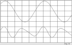
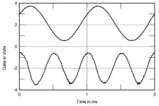
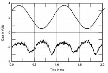
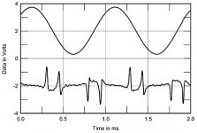
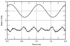
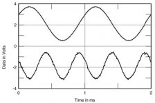
Very helpful for choosing the right OP-AMPs would be a diagram with the distortion waveform character (fundamental notched out).
In the attachment are to find such diagrams from some power amps, which I have heard in the last years and even tested and measured in the US magazine "Stereophile" (with my experience today, I would know which of these models I would not even unpack and test ):
Pass Aleph 3
Pass Labs Aleph 3 power amplifier Measurements | Stereophile.com
Solution 710
Soulution 710 power amplifier Measurements | Stereophile.com
bel-canto-eone-s300iu-integrated-amplifier
Bel Canto e.One S300iu integrated amplifier Measurements | Stereophile.com
accuphase-m-2000-monoblock
Accuphase M-2000 monoblock power amplifier Measurements | Stereophile.com
balanced-audio-technology-vk-56se
https://www.stereophile.com/content/balanced-audio-technology-vk-56se-power-amplifier-measurements
Halcro DM38
https://www.stereophile.com/content/halcro-dm38-power-amplifier-measurements
Graaf GM200
https://www.stereophile.com/tubepoweramps/997graaf/index.html
Bryston 7B SST2
https://www.stereophile.com/content/bryston-7b-sstsup2sup-monoblock-power-amplifier-measurements
Bryston 3B ST
https://www.stereophile.com/content/bryston-3b-st-power-amplifier-measurements
PS Audio Stellar M700
https://www.stereophile.com/content/ps-audio-stellar-m700-monoblock-power-amplifier-measurements
If there are such diagrams with the distortion waveform character (fundamental notched out) at different frequencies (e. g. 100Hz-1KHz-10KHz-20KHz) and different levels on different loads, one would find with a probability bordering on certainty that only very few integrated operational amplifiers would be suitable for audio applications.
The NE5534 (so as the dual version NE5532) that Mr. Douglas Self favors for many applications in audio stuff, so as all other OP-Amps with two gain stages inside of the feedback loop (even the OPA627/637/LT1028) are unfortunately not included therefore according sonic impressions of most listeners.
I have find out, that all integrated OP-AMPs with only one voltage gain stage (at whole a folded cascode so as an buffer stage) inside of the NFB loop provide good results on listening tests.
My favorites in RIAA phono and line pre-amps so as power amp front ends are AD797, AD817/AD825 (dual version AD826) AD844 and AD846.
Even the OPA604/2604 so as OPA134/2134 provide better results than OPA627/637, OP27/37 or LT1028 from the view of most listeners.
I don't know, why two gain stages inside of the feedback lope (like the circuit topology of "BLAMELESS" power amp are a disadvantage for good results on listening tests, but I guess, the THD waveform character is nearly triangular instead of sinusoidal.
By compare a OPA604 or AD817 against a OPA627 or LT1028 in a line stage of a preamp at a listening test the audible differences are similar to those by compare a Pass Aleph 3 single ended class-A power amp against a Bryston 3B or PS Audio M700 power amp (check out the attachments).
Whoever of the experts of measurement technique could create and post these diagrams for the most popular operational amplifiers ?
These have a much greater significance in relation to the sound character perceived by most music listeners than the most showed diagrams with THD+N vs. frequency.
The biggest disadvantage of all these considerations is that all exist distortions (THD+N) are lumped together in the diagrams and no distinction is made between THD components e. g. of a low order (inaudible up to around 1-2%) and those of a very high order, which always occur even with extremely low THD+N levels are still audible - go to fig. 3 under
http://www-f9.ijs.si/~margan/Articles/Class_B_Dist.pdf
(The fact that these diagrams refer to power amplifiers in non-Class A operation and not to small signal stages with OP amps doesn't matter for these fundamental considerations - so I think).
Very helpful for choosing the right OP-AMPs would be a diagram with the distortion waveform character (fundamental notched out).
In the attachment are to find such diagrams from some power amps, which I have heard in the last years and even tested and measured in the US magazine "Stereophile" (with my experience today, I would know which of these models I would not even unpack and test ):
Pass Aleph 3
Pass Labs Aleph 3 power amplifier Measurements | Stereophile.com
Solution 710
Soulution 710 power amplifier Measurements | Stereophile.com
bel-canto-eone-s300iu-integrated-amplifier
Bel Canto e.One S300iu integrated amplifier Measurements | Stereophile.com
accuphase-m-2000-monoblock
Accuphase M-2000 monoblock power amplifier Measurements | Stereophile.com
balanced-audio-technology-vk-56se
https://www.stereophile.com/content/balanced-audio-technology-vk-56se-power-amplifier-measurements
Halcro DM38
https://www.stereophile.com/content/halcro-dm38-power-amplifier-measurements
Graaf GM200
https://www.stereophile.com/tubepoweramps/997graaf/index.html
Bryston 7B SST2
https://www.stereophile.com/content/bryston-7b-sstsup2sup-monoblock-power-amplifier-measurements
Bryston 3B ST
https://www.stereophile.com/content/bryston-3b-st-power-amplifier-measurements
PS Audio Stellar M700
https://www.stereophile.com/content/ps-audio-stellar-m700-monoblock-power-amplifier-measurements
If there are such diagrams with the distortion waveform character (fundamental notched out) at different frequencies (e. g. 100Hz-1KHz-10KHz-20KHz) and different levels on different loads, one would find with a probability bordering on certainty that only very few integrated operational amplifiers would be suitable for audio applications.
The NE5534 (so as the dual version NE5532) that Mr. Douglas Self favors for many applications in audio stuff, so as all other OP-Amps with two gain stages inside of the feedback loop (even the OPA627/637/LT1028) are unfortunately not included therefore according sonic impressions of most listeners.
I have find out, that all integrated OP-AMPs with only one voltage gain stage (at whole a folded cascode so as an buffer stage) inside of the NFB loop provide good results on listening tests.
My favorites in RIAA phono and line pre-amps so as power amp front ends are AD797, AD817/AD825 (dual version AD826) AD844 and AD846.
Even the OPA604/2604 so as OPA134/2134 provide better results than OPA627/637, OP27/37 or LT1028 from the view of most listeners.
I don't know, why two gain stages inside of the feedback lope (like the circuit topology of "BLAMELESS" power amp are a disadvantage for good results on listening tests, but I guess, the THD waveform character is nearly triangular instead of sinusoidal.
By compare a OPA604 or AD817 against a OPA627 or LT1028 in a line stage of a preamp at a listening test the audible differences are similar to those by compare a Pass Aleph 3 single ended class-A power amp against a Bryston 3B or PS Audio M700 power amp (check out the attachments).
Whoever of the experts of measurement technique could create and post these diagrams for the most popular operational amplifiers ?
These have a much greater significance in relation to the sound character perceived by most music listeners than the most showed diagrams with THD+N vs. frequency.
Attachments
-
 Accuphase M-2000, THD waveform.jpg20.9 KB · Views: 496
 -
 BAT VK-56SE THD waveform.jpg36.4 KB · Views: 358
 -
 Halcro DM38 THD waveform.jpg16.7 KB · Views: 375
 -
 Graaf GM 200 THD waveform.jpg16.6 KB · Views: 2,581
 -
 Bryston 7B SST2 THD waveform.jpg19.8 KB · Views: 2,606
 -
 Bryston 3B THD waveform.jpg18.8 KB · Views: 2,618
 -
 PS Audio Stellar M700 THD waveform.jpg47.1 KB · Views: 2,701
 -
 Bel Canto S300iu THD waveform.jpg20 KB · Views: 315
 -
 Solution 710 THD waveform.jpg25.4 KB · Views: 351
 -
 Pass Aleph 4 THD waveform .jpg14 KB · Views: 361
Last edited:

Good stuff.
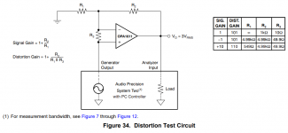
TI/Burr Brown has been going nuts over the past decade. The designers keep one-upping each other to the point that the latest Audio Precision test gear can't measure the distortion without a test bench to degrade the performance. They use a test circuit that causes the error voltage to be 100x larger.
Here's their latest, the OPA1611, with 15u% THD (!), and 1.1 nV/rtHz noise. Cost for the 1611 is kind of high at $3.02/amp in 100 piece quantities, but not crazy. I've never heard these, but I want to. Also comes in a dual, the OPA1612.
https://www.ti.com/product/OPA1611
Attachments
One thing you can say about D.Self ---he is consistent, most of what you have posted (from his book ) has already been published in his many articles ( and "flame level " arguments in EW/WW ) .
His "love " of the 5532 and his "hatred " of most things FET , so what you have here is one side of an argument --please read JLH,s replies as well as other audio design engineers in the letters pages plus rebuttal arguments in articles published in EW/WW .
I had over 20 years of reading all the comments/articles etc including--yes a partially sarcastic reply to a letter I sent basically backing JLH who---yes liked FETS and yes went by the sound reproduced not by distortion figures to such an extent he held a lecture with musical reproduction in a hall to put over his point.
He was also an advocate of Shunt Feedback --that caused another row with "someone ".
under
Parallel opamp: an extreme audiophile amplifier made of parallel multibrand op-amps
there are mentioned additional interesting operational amplifiers:
https://www.analog.com/media/en/technical-documentation/data-sheets/13645fa.pdf
(for simplifiied schematic go to page 11)
and
https://www.analog.com/media/en/technical-documentation/data-sheets/135859fb.pdf
maybe together with the AD8011 - go to
https://www.analog.com/media/en/technical-documentation/data-sheets/AD8011.pdf
https://www.analog.com/media/en/ana...number-2/articles/volume29-number2.pdf#page=4
CF-Opamp
and this discrete solution under
A Simple Discrete Current-Mirror IV Converter, à la AD844
a replacement part for the obsolete AD844
https://www.analog.com/media/en/technical-documentation/data-sheets/AD844.pdf
and AD846
https://www.analog.com/media/en/technical-documentation/obsolete-data-sheets/270284AD846.pdf
Last edited:
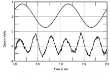
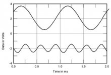
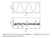
The situation may sometimes be more complicated than assumed here so far. For example, attached is a notched out waveform from an opamp used in an ESS dac. Even though the audio signal is sinusoidal, the distortion is not fully coherent with it. Why? Because the opamp has to deal with clock noise, with frequency shaped random noise from the dac's modulator, and with the audio signal, all combined together at the dac chip's analog outputs.
Attachments
Last edited:
I had over 20 years of reading all the comments/articles etc including--yes a partially sarcastic reply
to a letter I sent basically backing JLH who---yes liked FETS and yes went by the sound reproduced
not by distortion figures to such an extent he held a lecture with musical reproduction in a hall to put
over his point.
Imagine that. Do you have a link to the account of that JLH lecture?
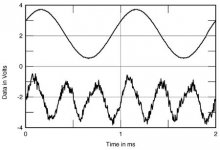
looks very similar to the eighth image from post #2 of Bel Canto's S300i/S300iu - driven by dual mono Icepower amplifier modules with switch mode power supply - go toThe situation may sometimes be more complicated than assumed here so far. For example, attached is a notched out waveform from an opamp used in an ESS dac. Even though the audio signal is sinusoidal, the distortion is not fully coherent with it. Why? Because the opamp has to deal with clock noise, with frequency shaped random noise from the dac's modulator, and with the audio signal, all combined together at the dac chip's analog outputs.
Inside the Bel Canto S300i integrated amplifier | Audiokarma Home Audio Stereo Discussion Forums
and
Bel Canto e.One S300iu integrated amplifier | Stereophile.com
In no case did I have too high expectations regarding the sound quality, especially in the high vocal range.
It is very clear that fragments of clock frequencies often give poor results in listening tests even with DAC's without integrated power amp modules.
Last edited:
Imagine that. Do you have a link to the account of that JLH lecture?
I have a "photographic memory" Rayma but I will have to look up that one as I am going back to the 80,s into the 90,s.
It was to prove a point (backhandedly ) to comments D.Self was making against him .
JLH was too much of a gentleman to reply in kind --its a pity more people are not like him , I actually got angry on his behalf.
Among old op amps, I've used a lot of TLO72, and a few 5532, but it was over 20 years ago.
Unless I've got a large number of them forming the signal path, I found the TL072 to be just what I needed. Low (enough) noise, no input bias, and ability to drive 2k and greater loads. No real audio signature, but useful for buffering, filtering and gain adjustment.
For pro-audio usage, there was really no substitute for a 5532. The need to drive a 600 ohm load ruled out most everything else. I found them to be great as buffers and gain adjustment, but less good for active filtering.
Other op amps I played with back in the day:
Tons of much higher performance op amps have been produced in the intervening 2 decades since I used op amps. I linked to the OPA1611 from TI/BB. AD/LT has mostly kept up.
I agree with you that some kind standard in the datasheets would be useful to help understand what the specific harmonic content is. You show residuals, with the fundamental notched out. I'd prefer to see FFTs of the harmonic content at a standard level--say 1V RMS. I can guess at those from the residual. Some RF line driver amps show this, but only for the 2nd and 3rd harmonics. Not what you are wanting, exactly.
I know to some extent what the harmonics are going to look like: 3rd harmonic is largest, followed by 2nd or 5th. 2nd and 4th harmonic are usually cancelled by good, symmetric design, so you don't usually see much of them. Then higher order harmonics will be low, but noticeably present. Output stage bias has been tuned high enough that these harmonics don't contribute much to the overall THD number, but not high enough to make them go away. All of these op amps have compensation that emphasizes higher order output stage harmonics by 6 dB/octave. However, if the harmonics are down in the 1.1nV/rtHz noise floor, then I doubt that I care about them.
Unless I've got a large number of them forming the signal path, I found the TL072 to be just what I needed. Low (enough) noise, no input bias, and ability to drive 2k and greater loads. No real audio signature, but useful for buffering, filtering and gain adjustment.
For pro-audio usage, there was really no substitute for a 5532. The need to drive a 600 ohm load ruled out most everything else. I found them to be great as buffers and gain adjustment, but less good for active filtering.
Other op amps I played with back in the day:
AD711, 712, 713 More expensive than a TL07x, lower THD, but not enough better to justify the cost. Hot stuff in 1992. Marked obsolete by AD.
OPA134, 2134, 4134 FET input amplifier that sounded markedly better than a TL07x. Lower noise, distortion, and the ability to drive 600 ohms. Worth the cost difference of the TL07x. Still an active part number.
AD844 is a video amp, and is awkward to use in general audio applications. Back in the day, some people simply thought slew rate was the only important spec, and higher was better. Those people were silly.
AD846 is a current feedback amp, and those are even more limited in how you can use them for audio. Sallen-Key filters would be tricky, for instance.
Tons of much higher performance op amps have been produced in the intervening 2 decades since I used op amps. I linked to the OPA1611 from TI/BB. AD/LT has mostly kept up.
I agree with you that some kind standard in the datasheets would be useful to help understand what the specific harmonic content is. You show residuals, with the fundamental notched out. I'd prefer to see FFTs of the harmonic content at a standard level--say 1V RMS. I can guess at those from the residual. Some RF line driver amps show this, but only for the 2nd and 3rd harmonics. Not what you are wanting, exactly.
I know to some extent what the harmonics are going to look like: 3rd harmonic is largest, followed by 2nd or 5th. 2nd and 4th harmonic are usually cancelled by good, symmetric design, so you don't usually see much of them. Then higher order harmonics will be low, but noticeably present. Output stage bias has been tuned high enough that these harmonics don't contribute much to the overall THD number, but not high enough to make them go away. All of these op amps have compensation that emphasizes higher order output stage harmonics by 6 dB/octave. However, if the harmonics are down in the 1.1nV/rtHz noise floor, then I doubt that I care about them.
but I will have to look up that one as I am going back to the 80,s into the 90,s.
I once saw a brief mention of it in an old Wireless World, but it was just a third hand account.
Also I have read his various writings on the subject.
Having done some related work myself, I strongly agree with him on this, as might many
should they actually listen to the sound, rather than to the measurements or their
preconceived notions.
Last edited:
You would think they would learn.
From what I've seen, not likely.
Did anyone ever correlate a measurement to explain why they sounded bad?It reminds me in the 70,s Japanese amplifier makers produced very low distortion amplifier ,way down in the -90db range but they sounded terrible. You would think they would learn.
Depends. For SD dac I/V? In that case, OPA1611/OPA1612 are very good bets. If they don't sound good in that application, I would look for problems in the implementation around them before going to other opamps. I mean, why assume the opamp is the problem? Just because someone decided to put a socket there?
Forget AD797, OPA627, 275, 1028 and all the other OLD opamps. I used them for a long long time but they are old and we have new opamps with MUCH higher SQ.
There is NO WAY that one of these opamps sound better then the mentioned OPA1612 and other new ones like OPA2192 etc. and if they do it is the fault of the circuit or whatever. As Mark pointed out OPA1612 is a terrific sounding opamp and if you have problems with its bold mighty extreme low bass performance or with the extreme high resolution and unfiltered highs you can use other new opamps with a more gentle sound like OPA2209, OPA2189 etc.
BTW, last year I crippled my €4.000 (DIY!) tube preamp with tube regulators and ELCAP free external PSU weighing over 20kg full of Lundahl transformers & chokes. Cos the OPA1612 do sound better with normal PSU regulators not to mention Jung regs...
Last edited:
- Home
- Amplifiers
- Solid State
- Choosing of best sounding OP AMPs for the lowest possible THD+N -really the best Way?