
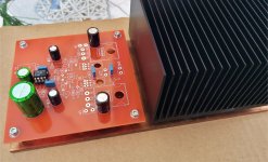
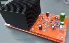
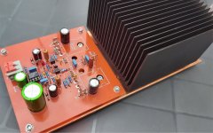
>I decided I’ll build the amp on a copper plate with a passive PC cooler
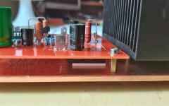
Please note, that S (source/emitter) pins of the fets are connected to the metal pad (different than hexfets (they use collectors)).
Both Fets DO NOT need insulators between them and Hetasink, as long as you keep both channels isolated.
In my build all fets (4 of them) were mounted to the common chassis, so I had to use insulators,
but in the Wiederhold amp, with single-die latfets, I used 2 copper plates, with passive heatsinks, and no insulators used.
Copper plates were mounted on common WOODEN slab.
Thanks Minek. You're right. It depends on how it will sound. If really as silky and smooth (tubish) as the original Philips, this amp definitely deserves a metal case.
I usually use AAVID aluminum oxide insulator under the power transistors (you can see these in the picture at post # 152) There are two reasons for this. One that Lazy Cat suggested this several years ago claimed that the sound will be a bit clearer if the FETs are moved a further away from the heat sinks. Interestingly, Denis Morecroft (DNM Audio UK) came to the same conclusion:
"To reduce the influence of magnetic interaction caused by such a large expansion of metal, we space the output transistors and regulators away from the heatsink, using aluminum oxide blocks. This material has no magnetic properties but good thermal conductivity.
This 5mm non-magnetic spacer gives a big increase in clarity and resolution. "
DNM Design Principles, Page 3 of 5 - Materials Technology
It also works well in VHEX+, it has very good thermal conductivity.
Last edited:
Heatsink metals are not ferromagnetic, so are not "magnetic" in the normally accepted sense of the word at all - they don't attrack magnets and are highly linear in their response to changing magnetic fields."To reduce the influence of magnetic interaction caused by such a large expansion of metal, we space the output transistors and regulators away from the heatsink, using aluminum oxide blocks. This material has no magnetic properties but good thermal conductivity.
They are conductors, so have a skin depth and eddy currents, but these will be irrelevant at audio frequencies - we're not winding a coil around these parts, any eddy current losses are tiny (and linear). This is true of the copper wire carrying the signal, and these see higher magnetic fields. Use of iron/steel wire or parts carrying high currents can lead to measurable non-linearities, but this is due entirely to the non-linear nature of ferromagnetism.
The extra capacitance caused by thin insulating washers is likely to be more real concern, as this represents capactive loading before the output inductor and could affect stability (especially with very fast output devices).
Al2O3 is an OK-ish heatsinking material, not nearly as good as the copper or aluminium of the heatsink, so on thermal grounds you still want the washers to be thin - there is a compromise to be made between thermal properties and unwanted capacitance, but standard thermal washers are typically not problematic (for RF power devices often BeO is often used for thermal paths due to its superb thermal conductivity, despite the toxicity risks). AlN is another high performance thermal material (way better than the oxide). Both BeO and AlN can be used in thick slabs with little penalty in thermal performance.
If you can afford it diamond is the best, way better than copper, but usually uneconomical!
"Why is R4 180R and not 150R as per the schematic? "
Because I use 36V instead of 42V supply voltage.
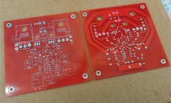
LatFet Amp Based on Philips AH578
Because I use 36V instead of 42V supply voltage.
LatFet Amp Based on Philips AH578
Last edited:
@ Minek I have a some questions.
1. According to the simulation, in order for the idle current to be 80mA (40ma/FET), the potmeter must be set to 90 Ohms. However, in the comment, you wrote "In actual build Pot was set to 50 Ohm (80mA idle current measured)". If I set the pot to 50 ohms in the simulation, the idle current is only 4mA on the FETs. Why is there this significant difference between the real conditions and the simulation? I don’t want to put a potmeter in the amp, just a fixed value resistor. What do you suggest, 50 Ohm (practical) or 91 Ohm (simulated)?
2. I have some ordinary red LEDs, but I don't know their technical parameters. The quiescent current of LED must be set to 1mA . If it is not exactly 1mA, how critical is that? I don't want to line up a potentiometer with the LED yet to set the exact value, I would leave the 560 ohm resistor as it is.
3. It can be seen on your actual build there's an 1 Mohm resistor parallel to the input. Why is this necessary?
Thank you.
Last edited:
>@ Minek I have a some questions
>3. It's can be seen on your actual build there's an 1 Mohm resistor parallel to the input. Why is this necessary?
Perhaps not necessary. I got this habit of adding these resistors at the input after building Elvee's circlophone, and his other amps.
All his amps have them, and I like these amps.
>2. The quiescent current of LED must be set to 1mA
This is not critical. This current will affect (to same degree) the BIAS of the output, but that can be adjusted by bias pot.
>1. BIAS pot
I would not try building it without the trimpot.. Apparently there was a difference between simulation and real life.
Reason - I'm just guessing here - tolerances of components (e.g. red led current mentioned above), hfe of transistors, LTSpice models not correct,....
Too many variables to decide on fixed trimpot value without actual measurements on the bench.
If you REALLY don't want the trimpot - start with small values of R (the lower the safer) and then gradually go up..
But it's easy to damage the PCB by doing this..
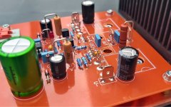
It's a piece of art.
I guess your rails will be lower than 50V ?
Thank you Minek! Yes. The amplifier will operate with + -36V Power supply. I expect a lot from this amplifier, as I mentioned earlier this circuit is more or less the same as ASR Emitter and B&W Aura VA-100. These two have an extremely clear tube-like sound, so I think I'll get a similar sound from your PHILIPS modification.
 Oh my Goodness! What a sound!!!
 Really? Great!!
Congratulations.
See symmetrical version of this amp (high slew rate, and very stable):
HexFet Amp Based on Philips AH578 and LMK
It can be built with Exicon latfets too..
My build is in progress - waiting for PCBs to arrive.
Congratulations.
See symmetrical version of this amp (high slew rate, and very stable):
HexFet Amp Based on Philips AH578 and LMK
It can be built with Exicon latfets too..
My build is in progress - waiting for PCBs to arrive.
- Home
- Amplifiers
- Solid State
- LatFet Amp Based on Philips AH578