Well I'm glad advice sought it was gut instinct just did not seem right to me.
Oh deary me now gotta pull those heatsinks off and that horrible grease to contend with. REALLY DO NOT LIKE THAT STUFF.
EMI thats why I twisted the cable usually helps plus I have some good quality screened cable plus they will have short runs. I think that will do the trick.
Yes there is grommet in there unfortunately adding the strips has increased the thickness of the ali to 7mm thick. So its getting a grommet with 7mm mounting gap. If it comes to it I'll just drill over a bit then it will only be 2mm thick on the strip. Be easier. Can be a ventilation hole ha ha.
One more thing bias not having any current or voltage readings for these does 45/47 volt seem about right for main rails? plus I need to measure amps so do you remove the fuses and measure across there? And if so would it be around 100mA mark? Just double checking again don't wanna short anything. There both quick blow 3.15 amp. Odd number!
Thanks Chris
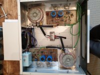
Friend, with due respect, you have a very foggy idea about what earth, physical, grounding, connection, signal, power concepts mean and that´s being polite.Basically they are both physically isolated from the heat sink so there's no earth connection there. I assumed this was normal method of instalation for these! Then via the screws and Solder tags and wire they are physically grounded to chassis. Now I know one leg is connected to the casing which is also physically earthed. Now I could of just connected them straight to the heatsink with no mica insulation or screw tab insulation. Then they would still be earthed via the heatsink but not physically. So are you saying they don't need an earth contact at all? And should be physically isolated from earth?
I'm assuming these are the power outputs? Not signal outputs?
NO CLUE would be more approppriate and you are working with dangerous things.
You seem to believe that using micas and a ton of grease keeps transistors insulated from ground, even if they are bolted to chassis and to boot one leg is also grounded.
IT DOES NOT WORK THAT WAY.
My crystal ball tells me this project will end disastrously, hope nobody gets hurt in the process.
Have to admit, the paragraph quoted by JMFahey had me very puzzled, too -- and worried for both your health, AND that of those venerable TO-3 outputs.
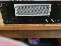
In your 2nd pic, are those the inputs in the lower left? I thought the convention was female XLRs when they're inputs.")
Cheers
In your 2nd pic, are those the inputs in the lower left? I thought the convention was female XLRs when they're inputs.
Cheers
Needs to brush up on his English language interpretation of wording and there meanings. In English language it's very easy to put things out of context by using snippets of information. Nothing personal just a bit of positive advice there.
Why I came on here never used those before only worked on valve gear and speakers plus valve test equipment. Had a read and look around and those T03 where directly earthed to chassis according to what I came across. Did not seem right to me hence came on here.
Anyhow digressed there. No those are the loudspeaker outputs another two the other side to go in.
The inputs think depends on balanced/unbalanced and would think you have a male and female input for those. Could be wrong!
Problem I have is holes had already been cut out on front of chassis so I'm trying to utilise those but it's not working out some holes too big or too small so I'm having to re cut holes and try to make it look tidy. Think should of run a piece of aluminium plate across the front at base filled holes with metal putty sanded and restarted. But I'll figure it out. So you will have 6 male xlr and 2 female xlr connections.
Pots will go up top and ill put aluminium plates over them.
Quite a bit of work but it'll get done.
Right not working 😕 this drilling with holes already insitu.
Ordered nice piece of ali strip 👌 thats going on front panel then make life easier plus finish will look much better. Looking awful at mo. Can't live with oh that will do approach. Plus be able to rivet in as I'm having to use oversized washers to keep nut and bolts in place plus will look neater.
Ordered nice piece of ali strip 👌 thats going on front panel then make life easier plus finish will look much better. Looking awful at mo. Can't live with oh that will do approach. Plus be able to rivet in as I'm having to use oversized washers to keep nut and bolts in place plus will look neater.
Unreasonable
You would better listen to JMFahey, he is concerned about your well being,
This is NOT A WAY TO TEST Just to START UP. THIS IS ENDANGERING YOUR AND OTHER PEOPLES LIFE.
Get these Wires shielded before anything else.
We do not want to see you getting your forums NAME BECOME True.
If using Mosfets, the HEAT-SINK needs to be grounded, to Center Ground of the Transformer or as you said Star-grounding. Mosfet are Super fast Transistors, and tend to Oscillate between the Heat-sink and them self. find the original Circuit, and check how it was actually designed.
And if you do not change your attitude, I think you soon will be a lonely man here, BTW that Grease you are talking about, isn't grease.! it's Heat- Sink Compound to help fill up the gaps between the washer the Transistor and the Heat-sink. And it will help to dissipate the HEAT faster from Transistor to Heat Sink.
Wipe it off and use new one. If you do not have new Heat Sink Compound, then LET IT BE AS IT IS, otherwise you will blow the TRANSISTORS, because of Overheating.!
With that fan in that box, you will sure not enjoy the music if you are going to use this amp in a closed room, this may was the reason that loudness of Volume control had been locked at some point, because the fan was too loud to listen on a normal Level. Note: In Europe we have .5 watt stated as ROOM Sound Pressure Level.
BTW, I think and I'm sure there are another 1000 on this Forum who think that JMFahey uses and understandable ENGLISH. I could not see any insulting speech of anyone here, may except you.
Take a note of what I wrote,, and think about.
Regards Chris ( that's my name) and I'm from Switzerland.!
But you still didn't told us where you from, but I guess from England.. Looking at the flag in your profile. If I'm wrong then correct me.
Nothing to be concerned about it's not permanent just to check it is wired up properly and to get voltage readings. That will all be isolated and done properly.
You would better listen to JMFahey, he is concerned about your well being,
This is NOT A WAY TO TEST Just to START UP. THIS IS ENDANGERING YOUR AND OTHER PEOPLES LIFE.
Get these Wires shielded before anything else.
We do not want to see you getting your forums NAME BECOME True.
If using Mosfets, the HEAT-SINK needs to be grounded, to Center Ground of the Transformer or as you said Star-grounding. Mosfet are Super fast Transistors, and tend to Oscillate between the Heat-sink and them self. find the original Circuit, and check how it was actually designed.
And if you do not change your attitude, I think you soon will be a lonely man here, BTW that Grease you are talking about, isn't grease.! it's Heat- Sink Compound to help fill up the gaps between the washer the Transistor and the Heat-sink. And it will help to dissipate the HEAT faster from Transistor to Heat Sink.
Wipe it off and use new one. If you do not have new Heat Sink Compound, then LET IT BE AS IT IS, otherwise you will blow the TRANSISTORS, because of Overheating.!
With that fan in that box, you will sure not enjoy the music if you are going to use this amp in a closed room, this may was the reason that loudness of Volume control had been locked at some point, because the fan was too loud to listen on a normal Level. Note: In Europe we have .5 watt stated as ROOM Sound Pressure Level.
BTW, I think and I'm sure there are another 1000 on this Forum who think that JMFahey uses and understandable ENGLISH. I could not see any insulting speech of anyone here, may except you.
Take a note of what I wrote,, and think about.
Regards Chris ( that's my name) and I'm from Switzerland.!
But you still didn't told us where you from, but I guess from England.. Looking at the flag in your profile. If I'm wrong then correct me.
Last edited:
"You would better listen to JMFahey"
I don't think "BETTER LISTEN TO" is an appropriate phrase.
he is concerned about your well being
I NOTICE ITS BEEN EDITED FROM ORIGINAL QUOTE WHICH NOW SAYS NO CLUE INTERESTING. It seemed more like calling an individual an idiot prior to editing.
This is NOT A WAY TO TEST Just to START UP. THIS IS ENDANGERING YOUR AND OTHER PEOPLES LIFE".
This makes no sense how do you test electrical circuits without any electrical input.
One can use a variac if one believes an item to be faulty. An electrical circuit needs voltage to be tested? If not what would you use to test a circuit? Individual items can be tested for faults which they have and new components added to the modules by myself. So I know it was safe to put a voltage into the circuit.
How will I be putting other people at risk? Of injury or death?
This is a hobby I have terminal cancer and needed something to keep my mind occupied I'm not an electrical engineer or run a business I do not fix other peoples equipment and have no intention of doing so.
"And if you do not change your attitude, I think you soon will be a lonely man here, BTW that Grease you are talking about, isn't grease"
I take that as a threat! What attitude? Can you extrapolate please.
In the UK we call it heatsink grease it's just a term. Is this just trivial "it is not grease" Again what help is that providing?
That reads as having an attitude. ITS NOT GREASE Why does one need to pick at such a meaningless point!
I asked if the heatsink had to be physically connected to ground as opposed to indirectly connected. Thank you for actually providing me with some positive information. It's star grounded as opposed to calling someone an idiot in a roundabout way.
I came on here for advice which I got from some very helpful people and which I was grateful for. Then bombarded no names mentioned with no helpful information just offensive references/quotes to what I had asked help for.
To date I have not ever had one piece of equipment blow up on me or ever been electricuted. I use a variac on suspect equipment and test it as the voltages are increased prior to that I look at all components and also test them. Bit more to it than that.
But to be honest just asking a simple question leads to this response is just amazing to me and is it really worth asking in the first place if your going to be insulted by particular parties. In my opinion no.
I'm in the UK not Australia and I'm sure I've mentioned that on my profile.
If I was a qualified individual I would provide people with help and advice and would definitely not pick out points and criticise them and provide no help at all.
So please if you can clarify what attitude I have it would be very much appreciated.
Cheers done quite a bit of reading up on this gear and must say very interesting. But what's even more fascinating is the different module configurations and although look relatively simple modules there actually quite difficult to get everything balanced out especially the voltages current and complementary pairs of bjts tips etc the output etc. But I'm getting my head round it now slowly buy getting there.
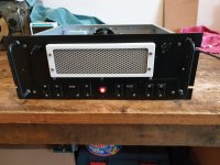
This one had to put a new plate across front panel as it already had cut outs and made it difficult to drill smaller holes next to or overlapping into existing holes. Anyhow just got some filling to do now and re spray then I can start getting the xlr connections pot etc in. One thing why do some people use a combination of phono jacks and xlr connectors on the input output connections? Is it just an older method or is there a specific reason?
This one had to put a new plate across front panel as it already had cut outs and made it difficult to drill smaller holes next to or overlapping into existing holes. Anyhow just got some filling to do now and re spray then I can start getting the xlr connections pot etc in. One thing why do some people use a combination of phono jacks and xlr connectors on the input output connections? Is it just an older method or is there a specific reason?
Phono connections are unbalanced, and have been the standard on consumer gear for decades.
XLRs can provide a balanced, and much more mechanically reliable, interconnect. Pro gear is balanced exclusively, and more and more hobbyists are running a pro piece or two.
I would strongly discourage using XLRs for the output connections. There are significant technical reasons. But the sole non-technical one utterly trumps all others: Sooner or later, if the gear lives long enough, those outputs will get plugged into something they shouldn't -- and it will kill that piece.
No doubt you are absolutely certain that will never happen, but as sure as the sun comes up every morning ...
Cheers
Bit late now already bought the xlr connectors plus not cheap so don't wanna be wasting them. I've got some decals for it so you know whats what. It's only to run one of my cd players through pair of 1970s H&H Loudspeakers. It won't be sold on by me so it's not gonna get brutalised at gigs etc. I'm also making up a switched fan module using a pair of thermosistor 12v relay etc as there's a 12v tap I can use for the relay and the thermosistors can be mounted between the BJTs on the heatsinks there set to go oc at 65°.
Schematics added for future reference managed to get hold of them.
Schematics added for future reference managed to get hold of them.
Attachments
Phono connections are unbalanced, and have been the standard on consumer gear for decades.
XLRs can provide a balanced, and much more mechanically reliable, interconnect. Pro gear is balanced exclusively, and more and more hobbyists are running a pro piece or two.
I would strongly discourage using XLRs for the output connections. There are significant technical reasons. But the sole non-technical one utterly trumps all others: Sooner or later, if the gear lives long enough, those outputs will get plugged into something they shouldn't -- and it will kill that piece.
No doubt you are absolutely certain that will never happen, but as sure as the sun comes up every morning ...
Cheers
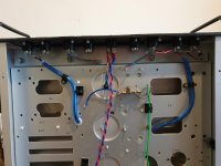
Well front panel done cut filled with abro steel putty good gear holes drilled re sprayed and connectors installed did not go as neat as wanted but not re doing all that so will have to suck eggs on that one.
Still fair bit to do.
Couple bits of advice sought
The output readings are 38.4mV left module right module 24.6mV. Having had read about as I have no voltage data to go by 24 seems about right but obviously the left one is roughly 12mV higher I also noticed the BJTs that side where getting warm whereas other side cool. So is the 24mV about right on output? If so to get the other balanced to same voltage do I need to turn the variable resistor counterclockwise and then turn clockwise until I get the mV reading same on other module or will it unbalance all the voltages and current?
The pots bit lost here obviously there are two terminals for that screen/earth and signal inputs tabs 1 &3⁹. Now the 2nd lug on pot is obviously for volume gain. Now do I just connect that to the output on speaker side or is there a particular way it needs to be done on these modules. It's gonna be for audio not guitar use.
I also decided not to star ground the heatsink as it was mentioned to do so. But on reading up this seems to be more related to the heatsink and components attached to chassis externally then rule of thumb is to ground it physically. Obviously grounded via chassis.
Any ideas on good quality circular rocker switches as the one I got has those horrible plastic shims to hold it in. Pretty crap really. Need one that can be screwed to chassis more secure. Looked at Bulgin ones look good bit pricey has anyone used them? If so any good?
Couple pics of progress not great deal done but getting there.
Attachments
Is it output offset that you're measuring - the 24½ and 38½ millivolt values? If so, they're a little on the high side, but not bad enough to do any soldering.
And is it with or without a speaker or dummy load?
The difference in heat sink temperature is hard to explain if there's no load. But I don't see any place on the MF100 schematic to measure bias, which WOULD correlate with a temperature rise.
PR1 is the bias pot. Since the schematic does not indicate which end of the pot is ClockWise, you'll have to measure to see which end the wiper is connected to. That end will be the Maximum Bias end, and it could go pretty high, so only make small adjustments -- at least until you confirm that the pot isn't noisy or intermittent. (Try Cramolin if so.)
Reducing the output offset may take a little more work. Maybe start by replacing C3 -- or if you don't have a fresh one handy, flip it in polarity -- and see if the offset changes in amount or polarity. If that doesn't give joy, a minor circuit mod (adding another trimpot) may be necessary.
I'm a little puzzled ..
The center terminal on the volume control, the 'wiper', often connects through another section of sheilded cable to the R1-R2 node -- I'm confused by the mention of 'output' and 'speaker side'. As far as I know, it's the same for any power amp -- a signal goes in one end, and comes out the other bigger and with more heft behind it. Same whether guitar or audio, except extra gain and tone options would be included for instruments.
I hope/trust you still have the cases of the output devices insulated from the heatsink.
Sorry I don't have any tips on rocker switches. Seems like just about all electro-mechanical parts have outpaced inflation for a decade or two now.
The work so far looks good. Love the big air filter.
Cheers
And is it with or without a speaker or dummy load?
The difference in heat sink temperature is hard to explain if there's no load. But I don't see any place on the MF100 schematic to measure bias, which WOULD correlate with a temperature rise.
PR1 is the bias pot. Since the schematic does not indicate which end of the pot is ClockWise, you'll have to measure to see which end the wiper is connected to. That end will be the Maximum Bias end, and it could go pretty high, so only make small adjustments -- at least until you confirm that the pot isn't noisy or intermittent. (Try Cramolin if so.)
Reducing the output offset may take a little more work. Maybe start by replacing C3 -- or if you don't have a fresh one handy, flip it in polarity -- and see if the offset changes in amount or polarity. If that doesn't give joy, a minor circuit mod (adding another trimpot) may be necessary.
I'm a little puzzled ..
Shockhazard said:The pots bit lost here obviously there are two terminals for that screen/earth and signal inputs tabs 1 &3⁹. Now the 2nd lug on pot is obviously for volume gain. Now do I just connect that to the output on speaker side or is there a particular way it needs to be done on these modules. It's gonna be for audio not guitar use.
The center terminal on the volume control, the 'wiper', often connects through another section of sheilded cable to the R1-R2 node -- I'm confused by the mention of 'output' and 'speaker side'. As far as I know, it's the same for any power amp -- a signal goes in one end, and comes out the other bigger and with more heft behind it. Same whether guitar or audio, except extra gain and tone options would be included for instruments.
I hope/trust you still have the cases of the output devices insulated from the heatsink.
Sorry I don't have any tips on rocker switches. Seems like just about all electro-mechanical parts have outpaced inflation for a decade or two now.
The work so far looks good. Love the big air filter.
Cheers
Thanks for that did think trimmer was for bias but as you mention cannot see where to measure from I'll look at schematic again. I think this one must be upgraded version as it's using buzz BJTs. The early version used the ones already installed.
Okay give that a go re C3 and reverse polarity I was pondering on that one.
The pots basically you have the input side live earth no different to rca connection then your output to speakers again live earth. But you have 3 wipers on pots so your only connecting up by using 2 wipers on input. But the 3rd wiper cannot see where it goes on schematic which is gonna give you the gain on the signal coming out of the output. Otherwise there's no volume if it's not connected into the circuit. Why asked if it connects straight to the ouput side.
Yeah those rocker switches cheap nasty as mentioned I don't like idea of just having plastic lugs holding it to chassis. Prefer nut and washer.
The fan is pretty good thanks and at full speed is only 40db other where over the 100 mark think be bit too noisy. I have two modules for that to switch the fan on/off was gonna set temp around 75° although I've read optimum temperature is 100°c seems bit hot to me if it gets that high.
Thanks for advice give that a go today C3 and I'll wire in pots.
Yes all insulated on heatsinks.
Cheers Chris
Okay. Waffling is fine, but there should be no direct connection between the volume control and the output -- we're good on that, right?
A gain control on just about anything electronic (For the moment let's ignore balanced circuitry and mixing board input attenuators.) will have two ground connections that both connect to the CCW end of the pot -- one goes to the source, one to the thing you want to control the volume of. The signal wire from the source will connect to the CW end of the pot. The wiper (center terminal) provides the signal to the thing to be controlled. In the MF100 schematic that's the joint where R1 and R2 are connected together.
Concerning temperature -- pretty sure anyone saying some certain temp is *optimum* is fooling somebody (themselves). Lower is better. Everything from power transistors to electrolytic capacitors last longer, and have fewer failures at lower temps.
Regards
edit: Umm -- the BUZ900 and 905 output transistors are actually lateral MOSFETs, not Bipolar Junction Transistors. The latter would require another probably couple stages of current gain to reach full output.
-- we're good on that, right?A gain control on just about anything electronic (For the moment let's ignore balanced circuitry and mixing board input attenuators.) will have two ground connections that both connect to the CCW end of the pot -- one goes to the source, one to the thing you want to control the volume of. The signal wire from the source will connect to the CW end of the pot. The wiper (center terminal) provides the signal to the thing to be controlled. In the MF100 schematic that's the joint where R1 and R2 are connected together.
Concerning temperature -- pretty sure anyone saying some certain temp is *optimum* is fooling somebody (themselves). Lower is better. Everything from power transistors to electrolytic capacitors last longer, and have fewer failures at lower temps.
Regards
edit: Umm -- the BUZ900 and 905 output transistors are actually lateral MOSFETs, not Bipolar Junction Transistors. The latter would require another probably couple stages of current gain to reach full output.
Last edited:
Ha ha there ya go shows not worked on these before it’s just shinning through ha ha.
Yeah all okay on pot like say thinking along lines of tone controls eq board etc just making over complicated in my head. Obviously for all that be complete re build adding in more circuitry.
Yes not sure why I put buzz as bjts already looked them up way back. Unfortunately on lot medication so brain not always on the ball as they say.
Goes to show reading info not always the right path to follow. Yes if running at low temperature gonna last longer for sure but think general consensus hotter better in relation to sound. Assume just personal preference.
Cheers Chris
- Home
- Amplifiers
- Solid State
- b k electronics mosfet 100 watt modules