Hi,
I am starting a new guitar amp project (solid state) and will be starting a thread on it at some point soon. I want to start by building a speaker protection PCB so that I don't destroy the speaker when testing it.
I was going to etch and drill something myself but I'm placing an order with JLC PCB in about a week's time for a different project so I thought it would be a good idea to lump it in with that. I also need to use a part that is only available in SMT so will need a two layer board.
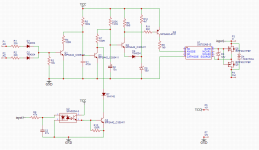
I've put together a design based around designs from Douglas Self and Rod Elliott. It incorporates Elliot's MOSFET relay with the Si8752 driver along with DC detection, turn on delay and loss of AC detection.
I've not built a speaker protection board before so I expect there are many things wrong with the design. Let me know what you think!
Thanks,
James
I am starting a new guitar amp project (solid state) and will be starting a thread on it at some point soon. I want to start by building a speaker protection PCB so that I don't destroy the speaker when testing it.
I was going to etch and drill something myself but I'm placing an order with JLC PCB in about a week's time for a different project so I thought it would be a good idea to lump it in with that. I also need to use a part that is only available in SMT so will need a two layer board.
I've put together a design based around designs from Douglas Self and Rod Elliott. It incorporates Elliot's MOSFET relay with the Si8752 driver along with DC detection, turn on delay and loss of AC detection.
I've not built a speaker protection board before so I expect there are many things wrong with the design. Let me know what you think!
Thanks,
James
Attachments
Hi,
I had initially ruled out breadboarding it, due to the SMD part. I realised that I could just use an LED with the same voltage drop in its place, though, and make sure that was getting the correct drive current.
I have now breadboarded it and, as a result, updated the design slightly. I have added a PNP transistor to drive the LED as there was not enough current available from the RC circuit. I could have reduced the resistor value but then I would have had to increase the capacitor value, which I didn't want to do. I also corrected an error with the diode orientation in the DC detector and changed one of the resistor values.
I have tested it with 30V rails and it seems to work as intended. There is a switch on delay of a couple of seconds and a fast switch off when DC is applied to the detector input or voltage is lost from the AC detector.
The DC detection thresholds are around +-3V and the signal needs to be below 1Hz to be detected. I have only been able to test the loss of power detector using a DC input as my bench power supply does not have any AC outputs.
I have attached the updated schematic.
Thanks,
James
Attachments
Hi James,
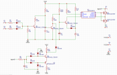
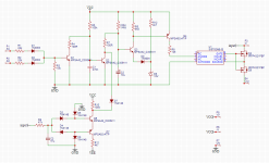
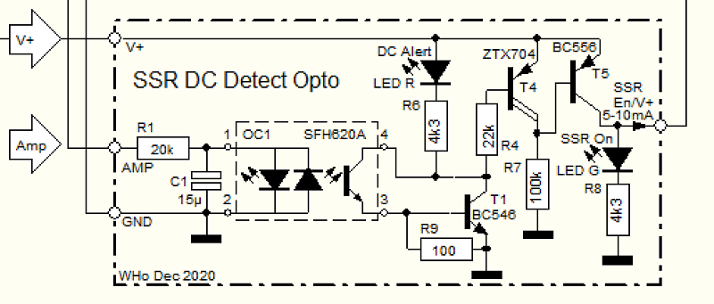
interesting topic for me as I'm currently developing a similar circuitry for my 4-way active Speakers. Maybe you're interested in my schematic as "food for thought". It was developed with a bunch of input in this forum.
As you see the DC detection is made simpler and because I have four ways, I have LED indicators telling which Amp shows DC. The FS signal is fed to each Amp in parallel, it comes from AC-lost detection, power on delay/muting and the remote on circuitry (not shown here).
Two detail hints on your SSR:
1. It seems advisable to place a 10V Zener across 8752 pins 5 an 8 to have a defined Ugs for the NMOSFETs., at 10V virtually all MOSFETs switch full "on".
2. A TVS device is advisable to protect the NMOSFETs against excessive Uds spikes, potentially possible when switching off the Amp and having long speaker wires connected.
So much for the moment.
Regards,
Winfried
Attachments
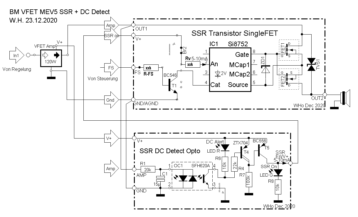
Thanks for the suggestions. I really like your optocoupler solution! It would cut out the diodes and two transistors as well as removing the need for the -ve supply rail. Looking at the datasheet, it looks like it can only handle a maximum collector current of 100mA so wouldn't be able to discharge the 10u capacitor directly. I'll order some to experiment with.
Thanks,
James
Thanks,
James
Hi James,
in order to increase SFH820A collector current capability maybe you want to consider a darlington configuration by the base of an external NPN transistor being driven by the SFH820A Emitter output (plus a 100Ohm Resistor in parallel with Base/Emitter of the external Transistor Gnd) and the two collectors tied together.
Regards,
Winfried
Attachments
I built it with Si8752 look here:SSR for power amps
Attachments
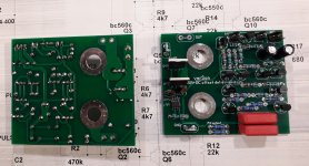
It might be worth looking at Q3 and Q4. When Q3 turns on it has the ability to pull a high current through the E-B junction of Q4 and then via the diode and Zener to ground.
The original version of that arrangement was (I think) used in Doug Selfs' Precision Preamp and there the Zener was in fact a resistor of 10k (your R12 would be 10k also).
If you want to keep the Zener then perhaps add a suitable base limiting resistor to Q4
The original version of that arrangement was (I think) used in Doug Selfs' Precision Preamp and there the Zener was in fact a resistor of 10k (your R12 would be 10k also).
If you want to keep the Zener then perhaps add a suitable base limiting resistor to Q4
Well spotted, thanks! I'll add a base resistor to Q4. I think 22k will be about right.
In 'Audio Power Amplifier Design', Self presents both the Zener and potential divider solutions, with the potential divider version touted as being cheaper than the zener. The problem with using the potential divider, he says, is that the capacitor will charge to full rail voltage and the voltage reference from the divider will only be one base-emitter drop below. A slight rise in rail voltage could then cause the transistor to switch off. He fixes the problem by adding a resistor in parallel with the capacitor, preventing it from charging all the way to the supply rail. I suppose I could do that too. I like the zener though, for no particular sensible reason!
Thanks,
James
It all depends on the supply voltage really. Any base resistor needs to be low enough to ensure TR4 saturates (no appreciable voltage across C and E when on). I would probably have gone for something like a 3k9 or 4k7 as a first guess.
Lets see... so you mention a 30 volt rail and you have a 15 volt Zener... that means about 15 volts available across any resistor. Say 2 milliamps base current for a high gain TR4 and you get around 7k5.
Lets see... so you mention a 30 volt rail and you have a 15 volt Zener... that means about 15 volts available across any resistor. Say 2 milliamps base current for a high gain TR4 and you get around 7k5.
I was estimating hFE for the Q4 to be between 20 and 40. With around 20mA Q4 collector current that would need 0.5-1mA of base current. 22k gives around 0.7mA.
I think where I'm wrong is in assuming that Q4 is in saturation and that, at this current, it isn't.
Thanks,
James
I think where I'm wrong is in assuming that Q4 is in saturation and that, at this current, it isn't.
Thanks,
James
Is this pcb available?I built it with Si8752 look here:SSR for power amps
")
I just had a play around with it. The transistor seems to be fully saturated with 4k7, there is no change in C-E voltage below that. I presume that means I should use a 2k2.
Thanks,
James
It does really, particularly if you are making a circuit available for a wide audience. It has to work reliably with all devices (transistors) that might be within the specified parts gain group. It also has to work reliably at possibly quite low temperatures where the gain becomes even lower.
Other options are to specify a specific high gain part that would allow reduced base current.
This is my updated design, I think it should be the final version unless I've missed anything. I'm still not sure about the choice of TVS across the output though.
I'm currently designing the PCB and using Faston connectors for the various connections. Is there are rule-of-thumb for spacing? I can't seem to find the info from a search.
Thanks,
James
I'm currently designing the PCB and using Faston connectors for the various connections. Is there are rule-of-thumb for spacing? I can't seem to find the info from a search.
Thanks,
James
Attachments
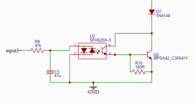
U2 driving the B-E junction direct from Vcc ? Its the same kind of problem as earlier. If the transistor in the opto is fully conducting then there is nothing to limit current flow.
R10 is really low as well. I'd juggle that and make R10 something much higher (say 10k at a guess) and add a base resistor.
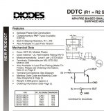
You could always use a 'Digital Transistor' (as we used to call them) like a DTC144. SMD only though as far as I know.
R10 is really low as well. I'd juggle that and make R10 something much higher (say 10k at a guess) and add a base resistor.
You could always use a 'Digital Transistor' (as we used to call them) like a DTC144. SMD only though as far as I know.
Attachments
- Home
- Amplifiers
- Solid State
- Building speaker protection board with MOSFET relays