Hans, for the umpteenth time, using various examples, I ask you to pay special attention to the Group Delay, which should be no more than 100 ns, as well as to its behavior far beyond the audio range. What is incomprehensible here?
Added a test for the lower frequency of the audio range.
High-class specialists have achieved similar results as a result of hearing examinations.
Added a test for the lower frequency of the audio range.
High-class specialists have achieved similar results as a result of hearing examinations.
Attachments
Hans, to you my repetition of “pay close attention to GDelay” sounds like a scratch on a record. I myself am already tired of repeating a seemingly common truth, or, as some colleagues say, I go in a circle “reinventing the wheel”.
Indeed, I just summarized the known facts from brilliant developers: Baxandall, John Curl, John Linsley Hood, Walt Jung, Jiri Dostal, Hiraga, Hawksford, Cyrill Hammer and many others and systematized them.
I have already described how I was asked to investigate the causes of poor sound in a conference room at a university. At the same time, with the help of a 32-band equalizer, the frequency response for sound pressure was easily set to a ruler. And listening to such a sound was impossible. As it turned out later, equalizers introducing only "linear distortion" only exacerbated the situation by introducing additional speed distortion. What is called one we treat - another we cripple. I will not repeat (enlarge the scratch).
Considering that everyone is pretty tired of the GDelay theme, I will round off. Then decide for yourself which direction you should follow: chase an increase in the number of zeros after the decimal point in the THD, or still strive to make the GDelay as small as possible
That would be good. Try to summarize why you think GD is important, and what you base that on, something of a reasoning, and tests that examine GD while trying to exclude other factors. In other words, the normal way of trying to discover something: coming up with a hypothesis (which you did) and test it to prove it must be true.
And, at least for me, an example like 'we used an equalizer in a conference room and it sounded bad, therefore GD is important' is not any proof. It is a very weak anecdote, a reasoning with lots of holes in it.
Jan
And, at least for me, an example like 'we used an equalizer in a conference room and it sounded bad, therefore GD is important' is not any proof. It is a very weak anecdote, a reasoning with lots of holes in it.
Jan
The conference room used 3-way acoustics. Each channel has 2 amplifiers with adjustable crossovers. At first I tried to find the optimal section frequencies, but this did not completely solve the problem.
Then I shot the frequency response of each speaker separately using a measurement microphone in the near field. There were serious problems with the frequency response.
In the low-frequency sections, the phase inverter was incorrectly calculated and tuned, moreover, the case had insufficient stiffness of the walls. The phase inverter was counted, the body was reinforced with additional stiffeners and struts inside.
In the mid-high-frequency section, it was necessary to completely recalculate and redo the passive filter taking into account the frequency response of individual dynamic heads.
After the specified improvements to the acoustic systems, the equalizer turned out to be with the controls set to "zero" and it was decided to exclude it, the sound only improved from this.
And this is not surprising, because the path has been shortened.
The sound engineer, a former musician, was very pleased, His friends, the leaders of jazz bands, the leaders of musical groups highly appreciated the sound.
Another feature of the Ampzilla amplifier is a soft turn-on, without "claps"
the music signal is a pulse signal rather than just a sinusoidal one. Apply a rectangular pulse signal to the equalizer, adjust and see what is output. He does the same with audio tracks. Therefore, it is necessary to use it very carefully, and it is better, if possible, to do without it.
the music signal is a pulse signal rather than just a sinusoidal one. Apply a rectangular pulse signal to the equalizer, adjust and see what is output. He does the same with audio tracks. Therefore, it is necessary to use it very carefully, and it is better, if possible, to do without it.
Attachments
Last edited:
Petr, there is a lot of good stuff in that document, but it is very hard to read. At several places, you talk about linear distortion, which has nothing to do with the point you want to make about GD (if that is it), and that linear distortion stuff constantly confuses me. Just delete all that!
This is a technical document, you are discussing technical issues. So don't insert statement "this amplifier sounded very good". I'm sure it did, but that is not the point. If it is the point, I can counter that I have a single ended tube amp which sounds much better than yours. Delete all that BS about better sounding, unless you do a controlled double blind test with statistically relevant results.
Again, WHAT IS YOUR POINT? We all understand that an amp with wider bandwidth has less GD, less phase shift and can reproduce a square wave better than an amp with lower bandwidth. Is that your point? Well, we know that. If something else is your point, then just tell us!
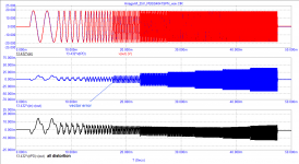
Edit: I should add that the 2nd part, starting with "An example of using a triangle signal in practice" gives some interesting illustrations on how to measure and document the differences between the two amplifier implementations. That is worthwhile.
Jan
This is a technical document, you are discussing technical issues. So don't insert statement "this amplifier sounded very good". I'm sure it did, but that is not the point. If it is the point, I can counter that I have a single ended tube amp which sounds much better than yours. Delete all that BS about better sounding, unless you do a controlled double blind test with statistically relevant results.
Again, WHAT IS YOUR POINT? We all understand that an amp with wider bandwidth has less GD, less phase shift and can reproduce a square wave better than an amp with lower bandwidth. Is that your point? Well, we know that. If something else is your point, then just tell us!
Edit: I should add that the 2nd part, starting with "An example of using a triangle signal in practice" gives some interesting illustrations on how to measure and document the differences between the two amplifier implementations. That is worthwhile.
Jan
Last edited:
Apply a rectangular pulse signal to the equalizer, adjust and see what is output. He does the same with audio tracks.
Of course no.
Music tracks doesn't contain such a signals, they nor can be produced with real musical instruments, nor can be synthesized with most of audio DACs.
Jan,
I'm afraid he doesn't understand your question or he doesn't know how to prove things.
The funniest of it all is that he thinks that it's us who don't understand him.
Hans
I think he's pretty smart but there is a huge language issue that prevents any reasonable discussion.
I mean, if my English is Google translated into Russian, does any Russian still understand it ;-) ?
Jan
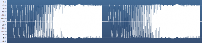
orjan, I see the test input signal like this. I used this signal to set up the recording-playback channel of tape recorders. Exactly in this form, it entered the input of the recording channel, and in the same form I observed it at the output of the playback channel, if the tape recorder was in good working order. Can I use it to test the amplifier? What do you think?petr, may I ask, how do you see the test input signal?
/örjan
Attachments
I mean, if my English is Google translated into Russian, does any Russian still understand it?
Yes.
Both of our languages are flexible enough to understand each other if you want to understand. But now the opposite is true, he forces you to accept his judgments.
I never found an argument against Graham's statements.But now the opposite is true, he forces you to accept his judgments.
As for my judgments, I have stated them in sufficient detail and I hope that my arguments are convincing, at least I do not see their refutation.
I never found an argument against Graham's statements.
Hard to discuss about "as wide as possible bandwidth", "as fast as possible speed".
Anyway you will be limited by power stage bandwidth/stability, VAS output current and hi-impedance point load capacitance.
Any good idea or sophisticated knowledge must point you how exactly reach those benefits.
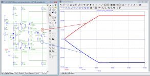
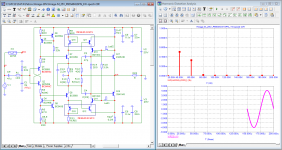
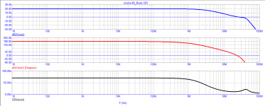
Now i see one way to achieve Graham's goals - make relatively simple amp with low feedback depth and very fast OPS, literally say - dominating pole somewhere at 100 kHz, first order and ~30-40 dB feedback depth at gain of +26dB.
The slightly modified amplifier by Hiraga satisfies these requirements. First pole 250 kHz, tPD = 22nSNow i see one way to achieve Graham's goals - make relatively simple amp with low feedback depth and very fast OPS, literally say - dominating pole somewhere at 100 kHz, first order and ~30-40 dB feedback depth at gain of +26dB.
Attachments
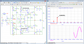
It is not so easy to obtain a great depth of NFB and meet the requirements for parameters that correspond to high sound quality.
The author of this development succeeded.
???? ?? ????????? ????? ???????? "??????????" ?????????
???? ?? ????????? ????? ???????? "??????????" ????????? - ???????? 33
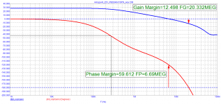
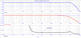
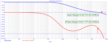
Judging by the parameters, the author is not only well versed in sound, but also strong in circuitry. The signal propagation delay time tPD = 70 ns from fractions of Hertz, up to 600 kHz, followed by a smooth falloff. The frequency of the first pole is quite high - about 20 kHz.
The NFB depth in the audio range is more than 85 dB, which provides negligible distortion.
The author of this development succeeded.
???? ?? ????????? ????? ???????? "??????????" ?????????
???? ?? ????????? ????? ???????? "??????????" ????????? - ???????? 33
Judging by the parameters, the author is not only well versed in sound, but also strong in circuitry. The signal propagation delay time tPD = 70 ns from fractions of Hertz, up to 600 kHz, followed by a smooth falloff. The frequency of the first pole is quite high - about 20 kHz.
The NFB depth in the audio range is more than 85 dB, which provides negligible distortion.
Attachments
- Home
- Amplifiers
- Solid State
- Musings on amp design... a thread split