Hi.
I have a quick question about the function of the "Mute Amp" pin on the Harman Kardon 670 (early 2000s model).
I am not very versed in electronic circuits etc, but it seems like you need to supply +5v to the pin, in order to "un-mute" the amplifier board?
I have bypassed all the relays, so it they shouldn't have any effect on the output.
Is there a kind soul, who would help a newbie out on the internet?
Kind regards from Denmark.
Attachments
Last edited:
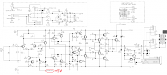
If you consider the front section as a totem pole differential amplifier. Q1 has the base held at ground or 0v through R3, Q2 has its 0v point taken from the output through R10.
To allow these components to work, they need a current source on the emitters through Q3, R9 sets the threshold of Q4 which limits the collector current through Q3, R4 holds the base of Q3 at -ve rail ensuring Q3 does not conduct. When a voltage is applied across R41 Q3 will conduct allowing Q1 & Q2 to conduct and amplify. R6 & R7 helps to balance the hfe of Q1 & Q2 and stops the gain from being too high which in turn may cause instability.
Lots of computer generated silly values for resistors I notice.
R6 & R7 helps to balance the hfe of Q1 & Q2 and stops the gain from being too high which in turn may cause instability.
Lots of computer generated silly values for resistors I notice.
So I wouldn't be wrong to put 5 volts on the "mute pin" since Q3 completes the "circuit", making current flow? I have to triple check.

I could change the gain by changing these values?
It's from Harman Kardon's own service manual. You gotta love the times, where you could look everything up, including the part numbers.
Harman Kardon HK 670 Service Manual — View online or Download repair manual
I have refitted the amp with a SMPS from Connex Electronix, a servo controlled potentiometer, multi coloured led rows for volume indication and relay control. All via an esp8266 board.
meter
Last edited:
I tested it, and it works. Thank you for the confirmation. Now I just need to eliminate this stuff from the SMPS.
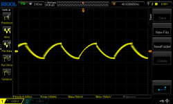
It's measured from the speaker output, and it's the same regardless of the set volume.
And it goes away if I disconnect the output of the pre-amp, into the amplifier board.
There are no ground loops, but oddly enough, if I connect an additional ground from the pre-amplifier's ground to the amplifier-board's source input ground, the noise reduces by 300 millivolts from one peak to another...
Could the pre-amplifier board be in need of shielding, or does it travel through the aux power output of the SMPS, and end up in the pre-amplifer though the 15v-0-15v is regulated to 12v-0-12v?
Attachments
Last edited:
Have you checked whether aux and main power supply ground on the Connex SMPS are connected as they seem to be originally? You haven't bothered to mention the model, and I can't seem to find any datasheets for them either way.
My guess would be that the ripple may be injected into signal ground on the preamp board. At 156 kHz, the usual 78xx regulators would not provide too much PSRR (and neither would typical amplifying circuitry), and on-board bypass capacitors would do the rest. The only ground path for bypass capacitor ground currents may be via the power amp connection, explaining why strengthening that reduces the amount of ripple seen.
Ripping out the power supply tends to be a major operation with more implications than you may be aware of. What motivated you to attempt it in the first place?
Have you checked whether aux and main power supply ground on the Connex SMPS are connected as they seem to be originally?
I connected them with common ground. However, I have moved away from this solution, and moved back to using a toroidal transformer for the pre-amp instead.
Single point ground from the pre-amp board to the ground on the SMPS. A star ground connection, if you will.
You haven't bothered to mention the model, and I can't seem to find any datasheets for them either way.
It's the SMPS800RE:
SMPS800RE | Connex Electronic
It's still have some problems, but I managed to reduce some of it. I still have to wonder though. Pushing in the +50v _v0 _-50v cables, changes the noise on the speaker output.
It could be the pre-amp board, or the SMPS which are the culprit.
It could bethe fact that drive the SMPS trough the boards original AC rectifiers.
The idea was to stop the current to flow back and forth between the amps and the SMPS.
There is audible hum on the the speaker output, like it's modulated into the switching frequency, or the other way around. I just can't locate where it comes from! I have tested if anything should be touching the floating chassis, but there is no continuity between any of the rails and the chassis.
I can't locate any ground loops either!?
If i touch the isolation on thet single positive audio input wire going into the amp boards, the noise increase. I only connected the "negative" shielding on the pre-amp side.
All the ground goes through a big "ground rail 0v" on the boards, and exits through the 3-pin power connector. The audio input and power input grounds aren't separate on the amp boards, so there might be problems on the board itself?
Perhaps the ground shouldn't be connected as a star connection at the SMPS, but rather meet on the amp board itself?
Pre-amp ground -> Amp-board <- SMPS ground.
What motivated you to attempt it in the first place?
A couple of years back the amp gave out. I located multiple problems with it back then, such as dead caps in tone-board, and the "logic" power supply.
Relays didn't work either.
Forward til today, and I wanted to reduce it's weight, so it could be placed on a floating TV-stand. And since it was gutted years back, there wasn't really any other options.
Last edited:
A picture of the whole thing would not hurt. How much of the amplifier do you have left? Are you following typical wiring guidelines (twisted V+/V-/Gnd etc.)?
Could you verify a few things for me on the Connex?
First of all, replace jumper GND Jmp (next to main output) by a resistor of 100 ohms to 1 kOhm, or leave open temporarily.
The thing I'd want to know most of all is which mounting holes are connected to mains IEC earth directly (and if not, where else they connect).
I'm afraid this might be all of them. That would be a problem because in a typical consumer integrated amp, the audio jacks are hard-mounted to the chassis back which serves as the (local) star ground. You do not generally want your unbalanced audio ground to be connected straight to PE, and as such neither the chassis. (Pro audio with balanced connections would be a different story. There this is generally desired.)
It would probably be a good idea to probe and follow the ground connections in the existing circuitry, so you can make a plan of grounding.
I would also like to know what the mains filtering on the Connex looks like. There seem to be some X and Y capacitors but I'm not exactly sure which is which and where they connect. (The thing between C29 and C37 is a common-mode choke, I think.)
Last edited:
Where is the rest of the schematic going to CN2
I rather think there is only 12V and not 5V available
I posted the service manual link. The amp is playing with 5v in the pin, as the schematic said.
I haven't had to time to look at the noise problem.
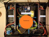
I have thought a little about it and when you think about it, the amp was actually originally two mono-blocks which shared ground through the audio input, and not on the power side.
The only thing connecting them on the power stage, was the transformer, and that wouldn't work. Center tap or not.
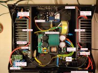
A picture of the whole thing would not hurt. How much of the amplifier do you have left? Are you following typical wiring guidelines (twisted V+/V-/Gnd etc.)?
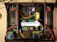
I have attached a picture with simple descriptions of the wires and a zip files containing the sound of the noisy hum.
The hum isn't that loud, and the amplifier plays very nicely, minus the hum of cause. The hum remains the same regardless of the potentiometers position/ volume, so the noisy hum is not coming from the pre-amplifiers output.
I had some cables refitted for the main power rails, so no, they are not twisted at this moment.
I also tried to move around the transformers inside the chassis and even move them out of the chassis, without it making any difference at all. So I assume it's not the censer wire in the SMPS' transformer picking up the electric field from the other transformers.
The thing I'd want to know most of all is which mounting holes are connected to mains IEC earth directly (and if not, where else they connect).
I'm afraid this might be all of them. That would be a problem because in a typical consumer integrated amp, the audio jacks are hard-mounted to the chassis back which serves as the (local) star ground. You do not generally want your unbalanced audio ground to be connected straight to PE, and as such neither the chassis. (Pro audio with balanced connections would be a different story. There this is generally desired.)
I have measured for shorts between the common ground and the chassis, and it appears that there are no connection. So the amp should be floating.
Attachments

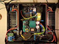
I have now put in twisted wires on the power rails, and it makes no difference to the hum.
It seems like there is a little reaction on the oscilloscope when a touch the chassis of the amplifier.
The amp is NOT earthed originally, and there is no earth in my apartment's wall sockets.
This haven't been a problem with other SMPS based amps before, and frankly, I do not know if it's the root of the problem?
Are you following typical wiring guidelines (twisted V+/V-/Gnd etc.)?
I am now.
First of all, replace jumper GND Jmp (next to main output) by a resistor of 100 ohms to 1 kOhm, or leave open temporarily.
Believe it or not, but my version of the SMPS does not have the jumper.
There is no continuity between the chassis and the 0v, according to my Brymen multimeter.
The thing I'd want to know most of all is which mounting holes are connected to mains IEC earth directly (and if not, where else they connect).
No earth on chassis at all. It's a floating circuit though.
The right mounting hole next to the mains input on the SMPS has an earth connection.
I would also like to know what the mains filtering on the Connex looks like. There seem to be some X and Y capacitors but I'm not exactly sure which is which and where they connect. (The thing between C29 and C37 is a common-mode choke, I think.)
I will try to take a good closeup picture, if that helps you.
Thank you for your help.

I can't get rid of the noise by anything I can come up with.
having the earth on the SMPS connected to the chassis reduces high frequency noise on the speaker output significantly, despite the chassis not being connected to mains earth.
But I can't get rid of the hum, no matter how the ground connections are arranged.
How I see it right now it could be 3 things.
1. The amplifier was originally only designed to have common ground through the signal path.
2. The SMPS is the culprit.
3. A combination of both.
I have now refitted the amplifier with a transformer, and it's now dead silent on the speakers.
Instead, I now have a mechanical hum from the chassis, but that was to be expected.
Is it really possible, that the SMPS let through a mains hum? I have tested it with another amp build with no ground loops, and it does the exact same thing, it would seem.
Should I "RMA" it, since it's only months old, and was never used before this build?
- Status
- This old topic is closed. If you want to reopen this topic, contact a moderator using the "Report Post" button.
- Home
- Amplifiers
- Solid State
- Quick question about the "Mute amp" pin on the HK670