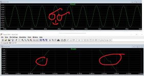
The board with no bias current will sound distorted. It takes less distortion than you can easily see on a scope for a sine to sound distorted. If you look at the zero crossings closely you might see the distortion.
The board with 185ma current needs careful measurement around the output stage to see if there is a fault or if it is just a problem with differing device characteristics.
The board with 185ma current needs careful measurement around the output stage to see if there is a fault or if it is just a problem with differing device characteristics.
Attachments
Ok understood -
What I have just done is swapped the boards over with respect to the output devices - and both boards are doing exactly the same with different OP devices - I guess that rules out any issues with these devices?
Kind of running out of time this evening - will go through the no quiescent board with a fine tooth comb (again!) tomorrow.
Be logical with your measurements.
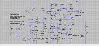
With the bias preset turned up there has to initially be enough voltage between the bases of TR103 and TR104.
If that condition is met then current flows in TR103 and TR104 and that in turn develops a volt drop across R118 and R119.
The voltage across these resistors has to also reach at least around 0.7 volts and then when that happens TR105 and TR106 in turn also conduct and in turn they develop around 0.7 volts across R123 and R127 and so bring the output transistors in to conduction.
Of the 10 milliamps bias current around half of that is flowing the final output transistors and the rest in the drivers TR105 and TR106.
Look at the voltages here. These are not absolutes in themselves but what is an absolute is the differences between various points such as the all important B-E volt drops and the voltages across the resistors in the output stage.
Attachments
Ok - so making progress here.
Yet again TR105 dead - this was the replacement 2N5322.
Went through ABSOLUTELY EVERTHING on both boards - the only semi damaged was TR105 (L) - so replaced this again.
C100 was measuring 0.01uF on one channel - TR100 measured out fine so didn't change that on either board.
Despite TR105 and TR106 being different devices on each board - standard RCA 38496/95 on R channel and 2N3520/22 on L channel both scope out pretty much identical.
I followed your circuit diagram and did an A-B comparison on various voltage points, although voltages differed slightly from the drawing, they were pretty much spot on with each other.
Scoped the outputs across frequency range 40Hz to 20KHz - negligible difference. Both outputs start to clip at 21.8V output at 1KHz.
My main issue is that I still cannot get Quiescent below about 185mA on either channel - this is with RV101 set to minimum.
obviously the rear heatsink is HOT after about 45 mins.
There is a small amount of 'fizz' and slight hum on R channel, L seems ok.
Is it possible the main OP devices have gone 'out of tolerance'
I have a TCR multifunction tester ( not sure how accurate these are!)
hFE TR1L=28
hFE TR1R=30
hFE TR2L=55
hFE TR2R=37
hFE TR106L=85
hFE TR106R=175 ( checked this figure 3 times)
hFE TR105L=77
hFE TR105R=66
going to investigate the noise on R channel later today.
As always, pointers, thoughts, suggestions more than welcome.
")
That is really super strange... it should read B to E on diode range with E going to the red meter lead.
Have you tested any unused versions of that same transistor to see if there is anything odd with the production. Without having one in front of me its hard to say but B-E failure by going open isn't a normal failure mode for a new semiconductor.
Being open B to E would fit exactly with virtually no quiescent current and distorted audio but the mid point would set OK... all that would indeed happen.
Are you sure the devices conform to the same pinout as the original? That's another possibility to look at.
So the devices came from Farnell:
https://uk.farnell.com/multicomp/2n5322/transistor-pnp-to-39/dp/9207082?st=2n5322
I don't have a spare 3522 - I only bought 2, 1 for each board, but I ended up using both in the same board!! - I am going to order more today so at least I can put them in the other board.
https://uk.farnell.com/multicomp/2n5322/transistor-pnp-to-39/dp/9207082?st=2n5322
I don't have a spare 3522 - I only bought 2, 1 for each board, but I ended up using both in the same board!! - I am going to order more today so at least I can put them in the other board.
Well there shouldn't be any room for error with that old T05 style can... it is really weird if they are failing open circuit.
Get some other types if you can. 2N5401 and 2N5551 (for the NPN) would be fine for test purposes in those driver locations. MJE340 and 350 are other super useful devices. Different pin out and case style but they are so handy to have around.
If you get more of what you are fitting now then test them before putting them in and also compare with the ones you have removed.
Are the output transistors the original RCA types?
Maybe if these have been changed to modern higher speed types you have oscillation.
If you short the input to your channels do you see any signs of oscillation on the output?
Usually, if the quiescent current does not respond to a control, it's due to some HF oscillation all else apparently OK.
I would be surprised, even so, because the amplifier is fairly heavily stabilised with a 100pF Miller capacitor and a 10nF on the pre-VAS transistor.
I have changed the output devices on a Quad build (not an original Quad but a home brew) to use modern types of transistor and doubled the frequency response of the circuit with a few other slight mods. (Also have another mod planned which lowers the distortion but not built/tested - still just in sim).
Yet another option is whether the electros are still low impedance. I think I read that you had changed some? But if electros go high impedance they may not be desoupling/coupling properly - but that could lead to oscillations again.
How are you measuring the quiescent current? Normally it should be by measuring the voltage across the emitter resistors of the output stage for the output stage current. If you are disconnecting the power rail and putting your meter in series that may well cause oscillations - check again while measuring the current.
Last edited:
Is this the first version with the two bias diodes, or the later one with Tr107?
If the former, did you change them? And if so, to what? And why? And can you change them back? The Vf of these diodes is extremely critical, and substitutions with 1N4148 for example are known not to work.
If the latter, replace Tr107 (BC549), and if that doesn't help try 1K8 for the 2K2 resistor around it, or the other way round, whichever it is.
Good point. The 1N4148 diodes are very popular but have a high maximum forward voltage. Possibly, the1N4448 would be better as that has a lower VF spec.
Alternatively replace the diodes with a variable bias as in the later version of the amp. if you don't mind a kludge on the board.
Alternatively replace the diodes with a variable bias as in the later version of the amp. if you don't mind a kludge on the board.
The output transistors are the original RCA 38494 units
I had to change a dead TR105 so I substituted with 2N5322 and also matched TR106 with 2N5320 - this is only on R channel, the L channel is original.
All the electros on both boards have been changed - and also both output caps ( 2200 uF Kemmet) and PSU caps ( 4700uF Kemmet)
...and I am checking current disconnecting the wire on pin2 and inserting my meter.
My 303 is the earlier unit with bias diodes - I have not changed these because there is nothing wrong with them - I was trying to avoid changing components for the sake of it, i'd rather find what is causing this non adjustable bias.
so........
L channel - this is the one with original semiconductors, minimum V across emitter resistors is around100mV and signs of distortion on the trace, I changed the original RCA drivers for 2N5322/20 - exactly the same result.
I will make a heatsink panel with a couple of old style 3055s and fly the wires onto the L board - it will save a bit of time stripping the rear heatsink down.
I'm just curious if the old output devices have deteriorated.
I strongly recommend you always measure bias current via the voltage across the emitter resistors, rather than by breaking the circuit and inserting an ammeter. Too many things can go wrong too quickly that way.
I've never actually never seen a 303 oscillate, and I've renovated hundreds of them. I think I would get interested in the Miller capacitors: there are two of them as mentioned above. You could also temporarily disconnect the Zobel network, which will be shunting some oscillation away, just to get a better look at things.
I've never actually never seen a 303 oscillate, and I've renovated hundreds of them. I think I would get interested in the Miller capacitors: there are two of them as mentioned above. You could also temporarily disconnect the Zobel network, which will be shunting some oscillation away, just to get a better look at things.
It is always possible for old transistors to have deteriorated. It rather depends on whether they have been abused, too. Those output devices were otherwise known as 2N3055, but would have been called the H version now. Their claim to fame was being robust. But if your 303 has had serious use it may be that the devices have deteriorated. RCA published thermal cycle data and showed devices lasting more than 10,000 cycles with moderate power cycling.
One advantage of the 303 is that you can measure the driver currents separately because of the 100 ohm resistor in the first stage and 10 ohm in the second. It might be worth measuring all six currents as you trim the bias pot. Should be about 600uA in the fisrt stage devices (60mV) and about 10mA on the second stage. If the current alters in those but not the output devices it could be that your o/p devices are leaky. The only leaky RCA devices I've seen were their MJ2955 epi devices after subjecting to too high a voltage. Their hometaxial base devices usually withstood voltages up to the breakdown. As far as I know they did not ship epi 2N3055's with the same 38494 label, but I may be wrong.
One advantage of the 303 is that you can measure the driver currents separately because of the 100 ohm resistor in the first stage and 10 ohm in the second. It might be worth measuring all six currents as you trim the bias pot. Should be about 600uA in the fisrt stage devices (60mV) and about 10mA on the second stage. If the current alters in those but not the output devices it could be that your o/p devices are leaky. The only leaky RCA devices I've seen were their MJ2955 epi devices after subjecting to too high a voltage. Their hometaxial base devices usually withstood voltages up to the breakdown. As far as I know they did not ship epi 2N3055's with the same 38494 label, but I may be wrong.
- Home
- Amplifiers
- Solid State
- Quad 303 quiescent