Hey, Sander, why don't you try this:
????????? ????????? + ???????
I couldn't resist, how's my Russian?

???????? ? ????????????, ????? ??????!
Very well, everything turned out clearly.
I couldn't resist, how's my Russian?
Got it!
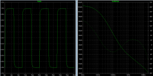
Try attached. Some dBs added at the same UGF.
Attachments
Last edited:
Got it!
Try attached. Some dBs added at the same UGF.
Thanks! But these simulations fall apart when I run the amplifier in balanced mode, which really is a requirement for me.
Pretty impressive performance, especially step response with high slew rate and zero overshoot.I run the amplifier in balanced mode, which really is a requirement for me.
Hans
Pretty impressive performance, especially step response with high slew rate and zero overshoot.
Hans
Thanks Hans, you're very welcome to offer suggestions to make it even better. What's that I hear? Is that your fingers itching to poke and prod the design where it tickles?
Last edited:
amplifier in balanced mode, which really is a requirement for me.
This is very bad idea to combine low-resistance input, high-voltage output and common-mode rejecting in one block.
First of.
Balanced straightly demands for precise balancing all signal path including PCB traces resistance, solder joint resistance, mechanical jacks resistance, wire resistance. Although some of them are out of your control and can't be redesigned in the right way. So the one possible way to workaroud this - is to have fairly high input impedance which in case will minimize all other imperfections.
Second of.
High voltage anyway will provide you with a higher currents, which in case will heat and disturbing resistances. But fairly precise resistances are the cornerstone of the common-mode rejecting. So the one possible way to workaround this - is to put dedicated differential receiver with a dedicated precise resistor network like LT5400.
Third of
Common mode rejecting are very demanding in modern conditions due to intrinsic ground-loop breaking if designed right way. I would forget about THD itself because most of the amplifier will an orders above and beyond of any speaker and no one can exain why ~120 dB feedback amplifier with measurable sounds audibly differ while different rail capacitors installed. Industry needs an another ruler.
This is very bad idea to combine low-resistance input, high-voltage output and common-mode rejecting in one block.
I'm not worried, please allow me to explain.
First of.
Balanced straightly demands for precise balancing all signal path including PCB traces resistance, solder joint resistance, mechanical jacks resistance, wire resistance. Although some of them are out of your control and can't be redesigned in the right way. So the one possible way to workaroud this - is to have fairly high input impedance which in case will minimize all other imperfections.
If you look at the schematic once more it is clear that only the input stage is balanced, the rest of the amplifier is single ended. If I wanted to make the entire amplifier balanced it would be a bridged topology (like the ExtremA) but I don't see the benefits here, partly because of the output power requirement not requiring such a topology and the fact that I want to keep the design simple. Please take note that moving to a bridged topology not only means an additional output stage, but also circuitry to keep the common mode in check.
Second of.
High voltage anyway will provide you with a higher currents, which in case will heat and disturbing resistances. But fairly precise resistances are the cornerstone of the common-mode rejecting. So the one possible way to workaround this - is to put dedicated differential receiver with a dedicated precise resistor network like LT5400.
There's no need, the input LTP is the only thing balanced about this design. If I wanted to improve on the CMR I could use a simple dual opamp at the input configured as a instrumentation amplifier. If I opted for that I would also choose to share the gain (20x) among the opamp and the discrete amplifier to further reduce THD+N.
Third of
Common mode rejecting are very demanding in modern conditions due to intrinsic ground-loop breaking if designed right way. I would forget about THD itself because most of the amplifier will an orders above and beyond of any speaker and no one can exain why ~120 dB feedback amplifier with measurable sounds audibly differ while different rail capacitors installed. Industry needs an another ruler.
PCB design is something I'm not worried about, nor CMR issue, one continuous ground plane usually removes most of the issues to begin with.
Balanced straightly demands for precise balancing all signal path including PCB traces resistance, solder joint resistance, mechanical jacks resistance, wire resistance.
I don't see the need for that. There is no need that both outputs are exactly identical in all respects. If you have a pos phase and neg phase output that are of good quality and reasonably close in gain, that's all you need.
Jan
Thanks Hans, you're very welcome to offer suggestions to make it even better. What's that I hear? Is that your fingers itching to poke and prod the design where it tickles?
There is no need that both outputs are exactly identical in all respects.
No.
Increasing the Common-Mode Rejection Ratio of Differential Amplifiers Through Precisely Matched Resistor Networks | Analog Devices
R1 and R3 on Figure 1 of that article includes all external components and straightly limits CMRR of the whole amp.

No. That doesn't apply here, a different case.
Heh, let's clarify, in what aspects different?
If you look at the schematic once more it is clear that only the input stage is balanced, the rest of the amplifier is single ended. If I wanted to make the entire amplifier balanced it would be a bridged topology (like the ExtremA) but I don't see the benefits here, partly because of the output power requirement not requiring such a topology and the fact that I want to keep the design simple. Please take note that moving to a bridged topology not only means an additional output stage, but also circuitry to keep the common mode in check.
The main benefit of the balanced( but really out of phase bridged, because output doesn't know balanced it or not) is not to dump high output current to signal reference ground with small, but not zeroed, impedance.
But about your comment.
You have no 'balanced' input stage. Basically your amp are redrawn differential receiver.
I wrote about different things, what to you will connect to the amps input? Are those blocks under your development?
How do you plan to regulate volume?
How any of the possible users will connect your amp to existing equipment?
Are you plan to combine SE and SuSy outputs of different signal sources in one input of your amp?
Again, your amp now is a differential receiver by topology. It anyway have low-impedance input. Both of this are normal in labour circumstances, but are wrong in DIY unpredictable world.
Bruno have perfect article "The G-Word" describing straightly this problem.
If I wanted to improve on the CMR I could use a simple dual opamp at the input configured as a instrumentation amplifier.
Again wrong. Instrumentation amplifier doesn't reject common-mode.
You need to first put a high-impedance buffer to break ground-related and common-mode currents and only then subtract common-mode from sum of common- and differential-mode input in the differential receiver circuit. Then you need to regulate volume, again buffer it's output with a some circuit which doesn't affected in its quality by source impedance and only the use power amplifier.
Also, keep in mind that power amplifier must be inverting, just because that noninverting amp have intrinsic nonlinear common-mode error vs common-mode itself and this error now dominates in total THD figures of the modern amps.
So, sorry, the one possible topology of the integrated poweramp is:
Buffer -> DifReceiver -> volreg -> buffer -> invAmp.
If you look at the amp as an operational differential amp, these things will matter imho. Resistor networks on inv and non-inv inputs should match precisely to yield max CMMRR - which translates to PSRR as well.
Question is, how much CMRR do you really need ?
An amp with an SE input has no CMRR at all, where you should keep in mind that CMRR only counts for a receiver when the source also has a balanced output and yes in that case it's better to have a balanced high input impedance.
Much more important IMO is the feedback resistor R10 because of the high voltages on this resistor where non linearities are taking their part.
The least one should do is to take a 0.5 Watt metal film resistors for R10 & R12 from the same (RN65) series.
You would be surprised how much distortion an improper feedback resistor can produce, IMO a more serious problem as CMRR.
Hans
You are almost turning CMRR into rocket science level, but it is not at all that complex to get it done.Again wrong. Instrumentation amplifier doesn't reject common-mode.
You need to first put a high-impedance buffer to break ground-related and common-mode currents and only then subtract common-mode from sum of common- and differential-mode input in the differential receiver circuit. Then you need to regulate volume, again buffer it's output with a some circuit which doesn't affected in its quality by source impedance and only the use power amplifier.
Also, keep in mind that power amplifier must be inverting, just because that noninverting amp have intrinsic nonlinear common-mode error vs common-mode itself and this error now dominates in total THD figures of the modern amps.
However an instrumentation amp suppresses CM, and yes it makes sense to use high impedance buffers in front while driven from a balanced source.
But at the end, a simple trimpot and a trimcap after the buffers is all you need if you really want to go to the limit for whatever reason.
Hans
you should keep in mind that CMRR only counts for a receiver when the source also has a balanced output
No. Things are much worse than usually keeped in mind.
Unbalanced connection really must be excluded from any equipment pretending to be HiFi. It's a really nonsense to mix ground coupling wire and signal reference potential in one conductor. So in case of unbalanced source first to be done is ground decoupling.
It's not a rocket science, but it's now an issue which need to be properly estimated and effectively resolved.
But at the end, a simple trimpot and a trimcap after the buffers is all you need if you really want to go to the limit for whatever reason.
Again - no.
Most of the designs are sensitive to signal source resistance, for example conditionally stable inverting amplifier could be easily run out of stability region due to this.
Last edited:
First of all, a conditionally stable amp is the last thing we want, don’t we ?
But even then will it be impossible to make things worse because trimming as mentioned should take place after the buffers, causing no effect on the source.
I can agree that it’s beneficial to prevent the usual double function of the gnd connection although probably true for 99% of all equipment.
Read ‘Pin 1 revisited, etc’ in Jan’s Linear Audio Vol. 10.
Hans
- Home
- Amplifiers
- Solid State
- Simplicity and elegance, feedback wanted!