One very real question with anything like this is that unless you have owned it from new or absolutely know its history then you have to assume that it may well have been worked on and possibly some parts are not correct.
That is always something to be aware of and something we do see crop up on the forum in repair threads.
That is always something to be aware of and something we do see crop up on the forum in repair threads.
So I agree with Mooly that ik makes sense to measure the voltage on both sides of R147 with reference to gnd, while you turn the pot R153 to confirm that this voltage stays at a stable -60 Volt.
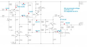
When that's O.K., concentrate on the right half, see image below what I mean with that.
Try to measure the voltages at the red dots.
When reporting this back, we will try to help you finding the problem.
Hans
OK, I will do these measurements tomorrow and report results as soon as possible. Let's see....
One very real question with anything like this is that unless you have owned it from new or absolutely know its history then you have to assume that it may well have been worked on and possibly some parts are not correct.
Mooly i do not have any clue about a potential hidden history of this device. It came to my hands with a minor problem, about six months ago. I was informed that it was working fine.
However, at that time, one side was a bit colder of the other, which forced me to suspect that something goes wrong with the bias, but i did nothing at that time.
Later the 'colder' channel started to present sudden distortions momentarily, but only hearable in difficult speakers (loads).
When the problem became stronger (about a month ago or 6 weeks) i decided to start investigating the problem. I could not imagine that it would be so serious and it also was a good opportunity to re-cap the whole thing (it has 4x51000uf/125V huge caps in the Vunreg (main power supply) and 4x1900uf/150V at the regulator (the Vpre-reg voltages).
However, when i opened it, i 'felt' that this device never opened before, although few doubts occur due to the models of the big capacitors (i read in forums that ML uses other caps' manufacturer, although this might be wrong due to many production versions/lines of these amplifiers).
Can't be really sure of anything...
Theodore
I wish you all the luck with your planned acquisition.Tomorrow i will go to buy a ML 336 (christmas present for myself-absolutely original device)
Theodore
I suppose you are talking about a set, don’t you ?
Hans
I wish you all the luck with your planned acquisition.
I suppose you are talking about a set, don’t you ?
Hans
Well, i finally did it....!
But guess what; the heatsink on the left side was looked a bit 'de-colorized' like from extensive heat.
I was again assured that everything is fine... the device never been repaired or even opened... bla, bla, bla....
But in any case i plan to perform a very good restoration (as soon as i finish with the 335). Of course i count on your assistance...
And no, it is not a set, just a stereo amp... i plan to use it with DCS Delius DAC/preamp.
Theodore
Hi Hans,So I agree with Mooly that ik makes sense to measure the voltage on both sides of R147 with reference to gnd, while you turn the pot R153 to confirm that this voltage stays at a stable -60 Volt.
the voltage on both ends of R147 is not stable.
It goes at max. 61V (i guess the reference voltage from zener).
It goes lower as i turn the R153.
When i have the max. -Vreg (~103,8V) the voltage on R147 (both ends) is -57,7V.
It decreases when i turn the R153 in one way, it does not increase over -61V when i turn the R153 on the other way.
Try to measure the voltages at the red dots.
When reporting this back, we will try to help you finding the problem.
Attached the diagram with the voltages. pls notice that the amplifier was cold (just start up). after a while voltages changed.
Theo
Attachments
They had to be checked
Lets go back to absolute basics... please measure these points and record what you actually have. The resistors are all low value and you can measure on either end.
1/ You have -60v applied to the base of Q115. This is the reference voltage. You can measure this on R141.
2/ When you set the output to its maximum (lets say -103 volt) what voltage do you have on R147? This is the base of Q116.
The two voltages should be equal when operating normally (no matter what the voltage is set to) but lets see what you actually have.
3/ What is the voltage on R145?
4/ What is the voltage on R146?
These should be similar as well.
So (references to gnd, and the amplifier is a bit warmer than before):
R141: -61,2V
R147: -60,1V
R145: -53,5V
R146: -39,5V
Theo
The voltage on R145 and R146 should be driving the regulated output more negative and that isn't happening.
We need to work with the above and follow through what is (not) happening...
If Q121 were open circuit it would do this.
If Q122 were very leaky it would also give the symptom you have.
Careful Base/Emitter volt drops can be revealing but I know you are not keen on that
You could swap the transistors around and see if your changes.
There is another way to attack this but I'll have to write it out and that is using the raw unregulated negative rail as a reference point for the meter readings and looking at why the series pass transistor is not being turned on sufficiently.
Also we can work back from the incorrect output by using that as a reference, at least for a couple of measurements.
As I always say, fault finding is all about gathering evidence and by doing as little invasive work as possible.
and that is using the raw unregulated negative rail as a reference point for the meter readings and looking at why the series pass transistor is not being turned on sufficiently.Also we can work back from the incorrect output by using that as a reference, at least for a couple of measurements.
As I always say, fault finding is all about gathering evidence and by doing as little invasive work as possible.
I will change both with new and see what is going on...
I have already started it...
OK, lets see what that brings

Careful Base/Emitter volt drops can be revealing but I know you are not keen on that
Not with these 'old' hands....
On a second thought, maybe i will try it....
WTF, UNBELIEVABLE....
i just saw that these transistor are not soldered!!!!!
Just strapped underneath!
I had seen that hey are not soldered on the upper tabs (like all other components), but i thought they were soldered on the bottom tabs. Since the holes are plated through there should be no problem....!!!!!
What kind of quality control is this.........
Attachments
I do have a Picoscope.
Last time i used it, was many years ago....
I have to check if i still have the relative software somewhere (laptops changed many times since then).
It's still very useful to measure Vreg- and Vreg+ with your Picoscope once you have repaired Q122.
The software has been updated many times, so just download the latest version.
https://www.picotech.com/downloads/_lightbox/picoscope-6
Hans
- Status
- This old topic is closed. If you want to reopen this topic, contact a moderator using the "Report Post" button.
- Home
- Amplifiers
- Solid State
- Mark Levinson No 335 - NO Bias in one channel / NEED HELP