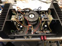
I have an ESP Project 36 that I've transplanted into a Hafler P225 chassis.
The original build article from years ago specified to use a 1"x2" piece of aluminum as a heat sink for the driver transistors.
I've found that this heat sink reaches 70C when the lid, up from 50-55C with the lid off. This seems a little high and I'd like to reduce the temp with a larger heatsink but I'm not sure how much larger or if I should use thicker material as well.
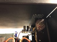
For example I replaced that 2" wide piece with 1" angle aluminum, essentially doubling the surface area and quadrupling the volume (1/16" v 1/8" thick), could I expect a significant temperature decrease or does it look like air flow is going to hold it back? There are vent holes above it but no vent holes in the bottom of the chassis.
I realize that there are many heatsink calculators out there but most require more parameter input than I can provided. Just looking for a nudge in the right direction.
The original build article from years ago specified to use a 1"x2" piece of aluminum as a heat sink for the driver transistors.
I've found that this heat sink reaches 70C when the lid, up from 50-55C with the lid off. This seems a little high and I'd like to reduce the temp with a larger heatsink but I'm not sure how much larger or if I should use thicker material as well.
For example I replaced that 2" wide piece with 1" angle aluminum, essentially doubling the surface area and quadrupling the volume (1/16" v 1/8" thick), could I expect a significant temperature decrease or does it look like air flow is going to hold it back? There are vent holes above it but no vent holes in the bottom of the chassis.
I realize that there are many heatsink calculators out there but most require more parameter input than I can provided. Just looking for a nudge in the right direction.
Attachments
Having build large numbers of class A power amplifiers what I can say is that your heatsinks are thick enough but while it looks nice and neat I would not put the output BJT,s right on the edge of the heatsink lip .
I would put them on the center of the lip and better still ( if you can engineer it ) and want to keep them there drill through the actual fins section and connect them directly onto that ---and yes I have done this in the past and it works --not so easy engineer wise but life is not that easy you have to put in to get out.
Dont believe me ?? --- buy a remote sensing temperature gauge that can be inputted to a computer to show a color spread of the heat .
Forced cooling (computer fan at the back)./QUOTE]
I run my PCAT 12 vdc fans at 9 v dc to cut the noise. This was added to a dynaco ST120 with angle heat sinks that had a serious meltdown tendency if used more than 3 hours at >10 W/ch.
In addition, flat rectangular heat sinks are fine for 1 hour use products, but fail to conduct the heat to the enviroment if the product is used 14 hours per day.
Commercial heat sink products with fins are much better actually getting rid of the heat.
One solution is mounting the driver to an aluminum angle, which is bolted with heat sink compound to the case bottom or side. Used in some commercial products, as my Peavey PV-1.3k.
Last edited:
Well, that's the chassis of a Hafler DH220, if I get it right, which had two pairs of power devices per channel, hence two TO3's on each lip. I'd not drill the holes for another TO3 into the middle, but turn the sinks upside down to get the power transistors into the lower holes, or mount them into the readily available lower holes. This would increase cooling efficiency somewhat. (And I'd get rid of those transistor sockets. But that's another discussion...but while it looks nice and neat I would not put the output BJT,s right on the edge of the heatsink lip.
I would put them on the center of the lip and better still...
 ).
).Best regards!
When I said "middle" I mean the active output devices directly connected onto the fin area rather than the flange therefore reaching the larger metal heatsink finned area directly.
I still wouldn't put very hot active devices so close to a heatsink edge ----bad engineering principles --check out the heat dispersion color --hotter near the edge.
I still wouldn't put very hot active devices so close to a heatsink edge ----bad engineering principles --check out the heat dispersion color --hotter near the edge.
Forced air cooling:
I did consider this and may revisit. Pretty easy to create a cardboard test lid.
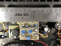
Output transistors:
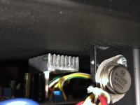
Driver transistors:
There is so little space around these transistors. I have a handful of small heatsinks but they all need to be hacked up to have a chance of fitting.
I did consider this and may revisit. Pretty easy to create a cardboard test lid.
Output transistors:
- I wanted to drill as few holes possible so I just tried this arrangement to see how it worked. I had recently dusted off this amp and didn't like its first donor chassis so I decided to see if I could squeeze it into the hafler chassis.
- I had a bad experience drilling a big heatsink years ago and didn't feel confident to try that just yet. Mounting directly to the heatsink base seems way beyond my ability. I have some surplus heatsink that would support this but wasn't ready for a chassis construction project.
- I suppose I could move one transistor to the bottom position to perhaps balance the heat sources. I've wanted to explore adding a parallel set of transistors in the bottom locations but I haven't had a chance to study how to do that.
- Why MJ211194 instead of MJ15003?
Driver transistors:
There is so little space around these transistors. I have a handful of small heatsinks but they all need to be hacked up to have a chance of fitting.
Attachments
If you use real ON ones, probably cheaper. Also more soa if I remember right. I keep MJL21194 around, they'll replace about anything TO3 npn.Why MJ211194 instead of MJ15003?
BTW single hole TO247 or 263 packages are a whole lot easier to drill a heat sink for than TO3. I won't even try TO3: I know my drills walk around and drill sideways in aluminum.
Yes, MJL21193/94 (omitting that L was a mistake, sorry!) are rather similar to MJ15003/04, but are somewhat faster and have expanded ratings and SOAR. But the main advantage here is that you'd drill only one hole per device and have the pins on the same side as the case. And they indeed are cheaper than TO3's.
Best regards!
Edit: Even cheaper, without any sacrifice, are NJW21193/94!
Best regards!
Edit: Even cheaper, without any sacrifice, are NJW21193/94!
Last edited:
I originally built this in 2005 and TO3 MJ15003 where both called out in the build guide for high power application.
I agree that MJL21194 would be easier to mount. If that’s what I was starting with, I definitely would have drilled the heat sink. However, at the time I was moving this to the Hafler chassis, most of the time and effort was laying out a new power supply pcb that would fit in the chassis.
I did hack up a larger heat sink to fit the drivers on one channel. Letting the amp warm up to compare the two channels.
But I’m thinking that the small vent holes in the lid are too restrictive. Will need to think on that. I hate to carve up the lid and would probably need to do the same to the bottom of the chassis.
Note there is a MJ21194 in TO3 package (with smaller screw holes) if you want to reuse the heat sink. Real TO3 take #6 screws, the new package only takes #4 or 3 mm screws.
Nothing wrong with MJ15003 but more expensive now and not often in stock. Note you can't match MJ15003 to MJ21194, you have to have all output transistors from the same process, and more purist, from the same batch. Even more, matching of individual transistors for Veb or gain at some defined current is highly recommended.
RE your vents, with bar heat sinks you better not leave the unit on for more than a couple of hours. You can make pseudofins on bars with a drill and a hacksaw. I use aluminum windowframe for TO220 drivers, which is shaped like a U, and drill 3 to 5 holes in it. It is the edge of aluminum that convects heat to the air, not the middle of the bar.
Last edited:
I had wondered about drilling holes in some angle aluminum. But with this new heat sink, it seems ventilation is the problem. The new heat sink is only about 7C cooler than the old. The open area above the drivers seems well below 20%.
I think next trick is to fashion a lid out of cardboard and experiment with open area. The bottom of the chassis has the same array of tiny holes as the lid. So I'll need to ensure I can get air in as well. Hopefully, I can do this just with lid modifications and avoid having to disassemble the entire thing.
I think next trick is to fashion a lid out of cardboard and experiment with open area. The bottom of the chassis has the same array of tiny holes as the lid. So I'll need to ensure I can get air in as well. Hopefully, I can do this just with lid modifications and avoid having to disassemble the entire thing.
Attachments
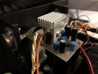
Convection cooled heatsink should have fins running vertically to work efficiently. The heat they emit causes air to rise creating air flow, that's how they work. Mounting them horizontally like you are showing doesn't give the air anywhere to flow from so only a small portion of the fin will actually be doing any cooling.
It looks like there are vent holes below and above the board. If you were to make longer sheet metal heat sinks bent into a U shape that extended past the edge of the pc board it would put them into much less obstructed air flow that would allow the convection cycle to work better.
It looks like there are vent holes below and above the board. If you were to make longer sheet metal heat sinks bent into a U shape that extended past the edge of the pc board it would put them into much less obstructed air flow that would allow the convection cycle to work better.
- Status
- This old topic is closed. If you want to reopen this topic, contact a moderator using the "Report Post" button.
- Home
- Amplifiers
- Solid State
- need advice on upsizing driver heatsink