mjona, the H suffix isn't universal and certainly never appeared on any original NAD3020 series amplifier or pics of the output semis I've seen. It seems that's why so many threads here have to point out the difference as a prelude to suggesting a fix. In any case, only the NPN version is/was offered as a hometaxial type with an H suffix.
As far as I know, a PNP complement identified as MJ2955H never existed so unless you're resurrecting a quasi-complementary design amplifier or you're the lucky type of guy who only blows NPN transistors, you may only have one option - fit epitaxials, add emitter resistors, use a Dim Bulb Tester for initial testing and take great care with bias setting and stability before loading it with a loudspeaker.
As far as I know, a PNP complement identified as MJ2955H never existed so unless you're resurrecting a quasi-complementary design amplifier or you're the lucky type of guy who only blows NPN transistors, you may only have one option - fit epitaxials, add emitter resistors, use a Dim Bulb Tester for initial testing and take great care with bias setting and stability before loading it with a loudspeaker.
Last edited:
I have that wrong. A PNP complement marked MJ2955H apparently did exist and was fitted to early series models but this wasn't disclosed in the parts list or schematic. I don't think semis other than those supplied by RCA or perhaps Motorola, were marked that way since the 1980s though. These amplifiers could need quite a few repairs in their lifetime and a change of semis easily confuses any attempt to trace the originals.
I have a 1978 RCA power devices handbook which is where I saw the H suffix 2N3055 but RCA became defunct in 1986 before this receiver was produced - 1988 according to Hi-Fi Engine.
Cross checking a Motorola Master Selection Guide from 1981 shows there have been two variants one complement pair with an A suffix and the other pair with none - this having the higher fT of 2.5MHz minima against 0.8MHz of the same. Motorola was spun off as On-Semiconductor in 1999 so you would be looking to see if the output transistors are branded as Motorola, whether these have suffixes or otherwise and whether the production dates are consistent with no substituted parts.
Cross checking a Motorola Master Selection Guide from 1981 shows there have been two variants one complement pair with an A suffix and the other pair with none - this having the higher fT of 2.5MHz minima against 0.8MHz of the same. Motorola was spun off as On-Semiconductor in 1999 so you would be looking to see if the output transistors are branded as Motorola, whether these have suffixes or otherwise and whether the production dates are consistent with no substituted parts.
I think 3020B, also introduced around 1988, marks the change to power semis from manufacturers other than RCA or Motorola. You can take that to mean from Eastern Europe, Japan and possibly South Korea or Taiwan itself because the keynotes with NAD and its imitators are all about cheap products with good sound sound quality. That also tells us a lot about the real demand for consumer audio products that has been with us for generations but most manufacturers would now rather avoid by catering to the wish-lists of museum piece collectors instead.
Let's just say that when hometaxial 2N3055/MJ2955 complements became unavailable from any source , NAD just stopped manufacturing the 3020/7020 and related models that depended on them. I've never seen any NAD model fitted with epitaxial 2N3055/MJ2955 or other TO3 semis either, unless it was an amateur repair job and the evidence of that is usually obvious.
NAD produced other models with standard Japanese audio transistors and some even had what you could call experimental and asymmetric output stages at the same time as the later 3020 series (i) and (e) which were still popular until the end. Interest had by then turned to the up-market PE (power envelope) designs, which were a version of class H and had good sound quality too. By then, all models were fitted with standard Japanese type audio power transistors.
NAD produced other models with standard Japanese audio transistors and some even had what you could call experimental and asymmetric output stages at the same time as the later 3020 series (i) and (e) which were still popular until the end. Interest had by then turned to the up-market PE (power envelope) designs, which were a version of class H and had good sound quality too. By then, all models were fitted with standard Japanese type audio power transistors.
I still recommend using On-Semiconductor epitaxial base 2N3055 and MJ2955 as replacements. You get what you pay for in consistency of quality and reliability.
Although RCA is history there are still advertisers having component stocks. One can see how legends arise as in the attachment.
Although RCA is history there are still advertisers having component stocks. One can see how legends arise as in the attachment.
Attachments

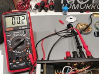
I went for the outputs you suggested. The amp has undergone a full electrolytic recap, all outputs replaced, all BD139 changed. So far so good...
I managed to set both DC offset and idle current as specified in the service manual with the original trimmers. I also added some heatsinks to Q408 and Q407 as they were getting really hot (barely could keep my finger on them), while those mounted on the outputs' heatsink were all rather cool.
My only big question is related to emitter resistors. AFAIK hometaxials were replaced in the late 70s and my model was launched in 1991. If there's no real need for them I'd rather not mess around with the PCB.
Any opinions?
Attachments
Every other brand used .1 to .51 ohm emitter resistors on epitaxial transistors. Brands with a reputation for reliability on the stage like Peavey used a lot of .50 ohms. Just because you don't see any "H" on the package doesn't mean NAD didn't source homotaxial transistors from some small semi house. Were many small semi houses 1980-1985. Now in To3 package there is On, ST, and the jolly roger sources.
If cutting the PCB and installing the emitter resistors is beyond your skill, buy something more reliable. NAD go $150-800 here on ebay, Peavey's with emitter resistors go as low as $30 for parts or repair plus freight. I don't know the market in your country, but you should be able to find some amp beat to death on stage, but reliable when cleaned up and upgraded such things as overage TO3 sockets, 30 year old overaged mica washers, dried up ecaps, or worn out fan.
I'm listening today to a MMA-875 I paid $30 for + $40 freight. Nothing wrong with it except a mono amp with two RCA jack mixed inputs, and a transformer output, which I think sounds fine. Have two of those until I recover from a burglar that carried off 4 SUV's of electronics, tools, and collectables. Writing everything down for the insurance company with prices documented takes forever.
Last edited:
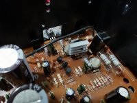
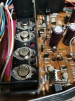
I'm sorry for the stupid question, but I'm not really sure where to put the resistors. The first picture is what my PCB looks like.
Since the emitters are in series with the breaker, placing one resistor for each emitter doesn't actually mean that the emitter of the MJ2955 has a resistor double in value? And wouldn't it be possible to add a single resistor between 2N3055 and the breaker for both outputs?
Thanks!
Since the emitters are in series with the breaker, placing one resistor for each emitter doesn't actually mean that the emitter of the MJ2955 has a resistor double in value? And wouldn't it be possible to add a single resistor between 2N3055 and the breaker for both outputs?
Thanks!
Attachments
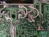
The feedback leg that wanders off to C428 doesn't matter much, but both Q416 and Q418 need their own emitter resistor. There can be cross conduction between the emitters if the driver circuits are not well behaved, and that doesn't go to the breaker and out. So you need two resistors. I'd put the two 3 to 5 watt resistors over on the right where those big holes are. Then cut the Q416 418 emitter leads short, drill holes through the board near the emitters for patch wires, and run wires through the board and bend them over to solder to the cut lead. Then the wires go over the the emitter resistors.
I can't really visualize your solution 
A photo with a modded PCB would help a lot but I only found a couple of older versions of the 3020 that seem to have different traces on the board (emitters in parallel with each other, going to a common point before the breaker, making it easy to place the resistors along the way)
A photo with a modded PCB would help a lot but I only found a couple of older versions of the 3020 that seem to have different traces on the board (emitters in parallel with each other, going to a common point before the breaker, making it easy to place the resistors along the way)
I'll try to describe it another way. Perhaps it will help with understanding the actual requirement when trying to follow suggestions here.
Like it suggests, each resistor is located at each output transistor emitter, inline or "in series with" the emitters and before any other connection. This means you will need to cut the 2 existing PCB tracks connecting the emitters together at the large pad where the output and feedback circuits also connect. You could use a miniature hacksaw blade or whittle away at the solder and copper with a scalpel or craft knife to do this, if you have no better option but use a suitable size drill for proper through-hole secure mounting of the resistors. You don't want them falling off or developing a bond failure in some overload situation.
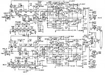
Also, search with your browser and read up on emitter resistors in the output stage and other topics related to distortion mechanisms of the output stage in other threads you will find here or just buy the books for systematic explanations and diagrams. This summary doc by Douglas Self covers a lot of related topics too and it's virtually free - the books are not. For reference, NAD's output stage would then become the basic EF type 1 design by Self's description at figure 13a - Distortion In Power Amplifiers
Like it suggests, each resistor is located at each output transistor emitter, inline or "in series with" the emitters and before any other connection. This means you will need to cut the 2 existing PCB tracks connecting the emitters together at the large pad where the output and feedback circuits also connect. You could use a miniature hacksaw blade or whittle away at the solder and copper with a scalpel or craft knife to do this, if you have no better option but use a suitable size drill for proper through-hole secure mounting of the resistors. You don't want them falling off or developing a bond failure in some overload situation.
Also, search with your browser and read up on emitter resistors in the output stage and other topics related to distortion mechanisms of the output stage in other threads you will find here or just buy the books for systematic explanations and diagrams. This summary doc by Douglas Self covers a lot of related topics too and it's virtually free - the books are not. For reference, NAD's output stage would then become the basic EF type 1 design by Self's description at figure 13a - Distortion In Power Amplifiers
After another look, I realised the R side power transistor in your pic. has traces connecting from both sides so you need to cut both tracks to the R side transistor emitter there, then fit the resistors on both L and R transistors but add a short link of insulated wire or heavy flex from the isolated R side trace to the common point between the emitter resistors. It's messy but so is any circuit modification to a power amp.
You have a schematic to follow now but as you say, there aren't many pics of that model nor detailed procedures and illustrations to follow for repairs or modifications, if any exist at all.
You have a schematic to follow now but as you say, there aren't many pics of that model nor detailed procedures and illustrations to follow for repairs or modifications, if any exist at all.
If you're going to fit modern epitaxial transistors to these amplifiers, you MUST add emitter resistors. If you dont, the amplifier will suffer thermal runaway and blow the outputs again.
You seem to be suggesting that hometaxial transistors don't have the same thermal properties as modern epitaxial types.
They still use the same base material silicon and the N and P doping materials in them are the same.
Epitaxial transistors are less costly to make and they have better high frequency characteristics which better suit them for audio power amplifiers.
If you look at Wikipedia re the NAD3020 you will see the mention of the outputs being 2N3055 and MJ2955 used by other manufacturers for amplifiers having outputs of 60 watts.
I looked at an image of the internals of one of these amplifiers and this is what I saw - these made by Motorola who also made hometaxial variants denoted by the suffix A.
The notion that these were used in the NAD3020 is a myth. Also this design was had a lot of novel features - such as being push-pull from input to output.
This should allow better push pull control over emitter currents in the output stage and so they left out the emitter resistors - expedient in a conventional design like a Self Blameless.
The set up procedure for setting the output current may be a bit finnicky but it has been proven to work.
I think the standing current is likely to be very low - the Gm curve of power transistors in the turn on region is curved making it harder to find the sweet spot.
The OP may replace his output transistors daily if he wishes to leave out the emitter resistors. My ST120 with 1970 RCA TO3 transistors and no emitter resistors was sure known for blowing the output transistors. In fact, I bought it that way. Added them, + fans, works years 14 hours a day. Sure a lot of threads on this forum for NAD with blown output transistors for it to be a perfect design.The notion that these were used in the NAD3020 is a myth. Also this design was had a lot of novel features - such as being push-pull from input to output.
Low idle current on output transistors sounds bad, IMHO. I've heard it myself on my amp OEM. Reviewers in 1966 panned the ST120 sound versus tube amps at the time. Takes 7 transistors on djoffe mod board to get my ST120 idle current up high enough to sound decent. Or some other mod to idle bias from the original dingy design. ***** the sweet spot, 20 ma brute force idle current sounds great.I think the standing current is likely to be very low - the Gm curve of power transistors in the turn on region is curved making it harder to find the sweet spot.
The power of a historic name! Used NAD are going from $300 (preamp only) to $3000 on Ebay last week. I got a working Peavey M-2600 for $105. <.1% HD @ 100 W. And a working switcher supply CS800s (.03% HD @ 400 W/ch) for $194.
Admittedly they will need new rail caps to achieve those max wattages.
Last edited:
Let's not confuse the different issues with complementary and quasi-complementary output stages. 2N3055 in any form, is only the NPN output side of NAD's 3020 amplifier anyway. I've seen a number of attempted repairs with stock epitaxial Motorola/Onsemi transistors, even in threads here but never actually seen a NAD30XX, 70XX etc. model fitted with their hometaxials from new. No doubt, some models did have at least one type of their hometaxial transistors - maybe deals were done too.
I've also lifted the cover off quite a few untouched NAD amplifiers and receivers that were based on the 3020 design. What was immediately apparent was that the output transistors came from mixed sources and manufacturers I never even new existed or produced these US types. Among them were Matsushita (i.e. National, Technics, Panasonic) Toshiba, Mitsubishi I think, 2 eastern Europe manufacturers and of course, RCA in the earliest examples but only of one type in those I looked at. I don't recall any original Motorola semis except those that were obviously replacements which had also failed.
On NAD failures generally, we need to realise just how cheaply they were built, the crude overload protection device, how many units were sold and just how old most examples are now. Like Dynaco's kits long ago, they were very popular just because they were cheap[/I] and every neighbourhood had one. NADs though, sounded sweet and warm at low, personal listening levels and they were distributed everywhere around the globe. ergo - there have to be a lot more failures/ problems by sheer force of numbers, like 1.1million basic 3020 model amplifiers and probably more than double that number in receivers, derivative and renumbered but otherwise similar models over the following decades.
Article and references here: NAD 3020 - Wikipedia
I agree that the 3020 was built to a budget. I looked up an old thread you contributed to which gave an internal view of the internals. This showed the output devices used for that particular example were made by Motorola and have a date code of 8205.
These were in the old dull finish TO-3 cases which were phased out when the shiny finish versions with the designation TO-224/AA slash TO-204AE arrived on the scene ( reference Motorola Master Selection Guide and Catalogue 1984).
NAD were new on the scene and needed to built a good entry amplifier as cheaply as possible. They would have bought up any new old stock parts if they were available at a reduced price.
There are two reasons why their preference would be for epitaxial devices.
These were introduced by Fairchild and they cost less than hometaxial devices to manufacture and they could undercut their competitors on pricing. No manufacturer stood by and watched their market going down the drain.
Secondly epitaxial devices have better high frequency performance. These have fT of 2.5MHz compared with 0.8MHz for hometaxial.
With the latter there are problems due to phase shift arising at lower frequencies and dealing with this limits nfb to an even lower frequency with compensation.
- Status
- This old topic is closed. If you want to reopen this topic, contact a moderator using the "Report Post" button.
- Home
- Amplifiers
- Solid State
- NAD 7020i sudden death