If the test points are around R456 which appears to be 1 ohm, then 28 mv is 28 ma and 22 mv is 22 ma. 22 ma is an entirely adequate idle bias current IMHO, but you may adjust until you get 28 if you wish. Djoffe designed the idle control circuit for my amp for 20 ma idle current. It doesn't start sounding bad until below 6 ma.
The output stage in this circuit is different than the ST120. The emitters of the drivers are cross coupled by a resistor so these remain "on" over the crossover point.
The arrangement is referred to as EF2 and an early version of this scheme is shown as an application in the RCA Power Devices Handbook.
Forty years ago I built one of these, and there are plenty of copy cat versions of Self's Blameless Amplifier using EF2 output stages on the current scene. The emitter resistor values chosen by Self of 0.1 Ohms have been adopted in the copy cat versions I have seen.
On the question of set up, if the fuses that protect the output stage were blown open circuit then you could solder 100 Ohm resistors across the ends and put them back in their holders while you adjust the output Iq setting.
@zenzaman,
Did you look at the youtube video I mentioned in post 44.
The reason I suggested removing the fuses was to see if the driver stage was working. There is more to take from that video than this. Take some time to think this over - the brain does not turn off problem solving when you doing other things or when asleep - answers can come from nowhere.
I learnt several years ago that relying on internet images to date or characterise electronic devices is unwise. Pro. repairs can be near invisible and the parts you may presume are factory original, turn out to be earlier replacements since the pic you see could well have been taken after a major repair/refurb job to show off the handiwork or after cleaning, just to get better offers to take it off the poster's hands. More confusing; amateurs may have used reclaimed or their own NOS parts to get the thing working..........The year code in the images give the year code as 1990 so they were not old stock at the time of manufacture and the NAD 7020 company part numbers end with M....What have you got to say about this.
I wrote earlier that I've never seen NADs with all-Motorola output semis and I can only speak for the many unusual, unexpected brands I've seen that were always different, NPN to PNP type in versions I've seen, other than those in the first and 3020A series which generally, were both RCA branded. By the time of the 3020i and e series, things had changed and it seemed someone was now scraping the barrel for any old stocks of the hometaxial NPN type. You could say that was a price issue but new stock 2N3055s had been dirt cheap for years.
I'm convinced that adding emitter resistors improves reliability for epitaxials, even if its only about the NPN side of the complementary pair. That's what matters when you don't know what the owner expected from an old and cheaply built 20W amp. where the norm for such products is more like 50-100W. People tend to look at size and weight of amps as indicators of power limits but I think we know how inaccurate or irrelevant that can be.
I'd go on about practical experiences but I think this branch of discussion should be in one of the 2N3055 threads here, otherwise it derails the thread.
Last edited:
Of course adding an emitter resistor in one side only will improve the reliability. Because the original RCA devices would be hometaxial NPN (with a built in resistor) and an epitaxial PNP (without, because that was the only thing available unless you wanted germanium). Doing the mod that way would put the performance through the crossover region as much like the original as you can get with modern parts. And you don’t technically need resistors in both sides anyway, from a thermal stability standpoint. It’s usually customary, and would be theoretically correct if the + and - sides were otherwise matched. They weren’t too well matched back those days anyway, even if both were epitaxial.
I learnt several years ago that relying on internet images to date or characterise electronic devices is unwise. Pro. repairs can be near invisible and the parts you may presume are factory original, turn out to be earlier replacements since the pic you see could well have been taken after a major repair/refurb job to show off the handiwork or after cleaning, just to get better offers to take it off the poster's hands. More confusing; amateurs may have used reclaimed or their own NOS parts to get the thing working.
I wrote earlier that I've never seen NADs with all-Motorola output semis and I can only speak for the many unusual, unexpected brands I've seen that were always different, NPN to PNP type in versions I've seen, other than those in the first and 3020A series which generally, were both RCA branded. By the time of the 3020i and e series, things had changed and it seemed someone was now scraping the barrel for any old stocks of the hometaxial NPN type. You could say that was a price issue but new stock 2N3055s had been dirt cheap for years.
I'm convinced that adding emitter resistors improves reliability for epitaxials, even if its only about the NPN side of the complementary pair. That's what matters when you don't know what the owner expected from an old and cheaply built 20W amp. where the norm for such products is more like 50-100W. People tend to look at size and weight of amps as indicators of power limits but I think we know how inaccurate or irrelevant that can be.
I'd go on about practical experiences but I think this branch of discussion should be in one of the 2N3055 threads here, otherwise it derails the thread.
Unlike you I will keep my comments brief. It was a human error which led to the situation that zenzaman finds himself in now.
The amplifier had been working well enough for about 30 years before this. It should have been a simple matter to have replaced the failed outputs with devices of the same kind.
According to HiFi Engine the 7020 came out in 1988.
The date code for 1990 on the output transistors suggests the date of manufacture would be close to that time.
Zenzaman included an image with post 44 showing the underside of the pcb which shows no signs of any prior service work or modifications.
You are looking at an actual case not some questionable image from the internet.
I think the circuit is worth studying to see why it earned the reputation it came to get but that is no concern to anyone here except me. I will keep my thoughts on this for another time.
@zenzaman,
Did you look at the youtube video I mentioned in post 44.
The reason I suggested removing the fuses was to see if the driver stage was working. There is more to take from that video than this. Take some time to think this over - the brain does not turn off problem solving when you doing other things or when asleep - answers can come from nowhere.
I must confess I only watched it now. But I did a similar test of sorts, by mistake. I lost one of the plastic bushings that go in the mounting holes of the output transistors so I had to buy something as a replacement. The only things I found were some sort of distancing / isolator bushings (https://www.tme.eu/html/gfx/image_3594.jpg) and used them for all outputs, not realizing they would actually isolate the collectors from the PCB. The amp powered and it felt like it sounded funny but it was late at night so the volume was very low. I initially thought it had smth to do with the idle current as the outputs were stone cold, while the rest were warm (and some quite hot - Q407 and Q408). Only the next day the actual error struck me.
I listened to the amp yesterday for a couple of hours at various listening levels (nothing too high - I've got neighbors) and I had a couple of intermittent left channel cutouts that I'm inclined to blame on a dodgy volume pot since they went away after adjusting the volume.
Also, after adjusting DC offset and idle current on a DBT, when powering it to full outlet voltage two fuses blew (I think they were the fast blowing type). I replaced them, powered it up on the DBT again, then full voltage and finished the adjustment without any other mishap. I have no idea what happened but I died a bit inside
") )
)Looking at the circuit diagram re Q407 this in combination with Q405 are causing current enough to give a voltage drop across R437 68R of 1.1 Volt the result is 16 m.A.
These transistors BC556 and BD139 form the Vas with the latter serving as a buffer which can handle that level of current. As a complementary feedback pair there should be good thermal stability in the Vas.
These transistors BC556 and BD139 form the Vas with the latter serving as a buffer which can handle that level of current. As a complementary feedback pair there should be good thermal stability in the Vas.
I found a clearer circuit diagram. This covers the 7020i and the more powerful 7225 pe which looks identical except for the supply rails which are higher. Voltages at test points on the 7020i which is copy of the 7225pe show the same voltages applicable to the latter - a draughtsman has slipped up.
I worked out the Vas current from the 7225 pe. The current level in the 7020 should be lower than 16 m.A.
In view of your comment about the intermittent cut out in the left channel I recommend you check the voltage drop across R437 and R438 to work out what the current level is in each channel.
I worked out the Vas current from the 7225 pe. The current level in the 7020 should be lower than 16 m.A.
In view of your comment about the intermittent cut out in the left channel I recommend you check the voltage drop across R437 and R438 to work out what the current level is in each channel.
Last edited:
Post # 89 # 90 are IMHO about the hot Q407. I think the 16 ma quoted in those posts talks about the currrent in Q407.
28 mv across 1 ohm of R455 should be fine, with emitter resistors. 20 ma is nominal in my quasi comp amp which mjona seems to feel has absolutely nothing to do with fully comp amps. I think that opinion is a little strange. Turn down to 20 ma if you are worried.
Personally I'd put a heat sink on Q407 the VAS. Lots of amps that need repair in the forum have blown a VAS transistor. The heat sink on them costs the manufacture ~$.30 in part and about $1 in labor since they don't fit pick & place machines. A heat sink costs the individual about $.60. Or less if you make it out of scrap aluminum, as I did. Not installing a heat sink costs the individual an hour or 2 taking the amp apart again if it blows Q407.
BTW I've found a vendor surplussales.com who alleges he has 2n3055H transistors. The picture doesn't show RCA or Motorola either. Logo is LO in an oval and EI in a circle. He doesn't deal with the source of most fakes overseas, he buys stuff from the US military & industrial auctions. However he doesn't guarantee anything he sells, and sold me "yellow" LED that were actually red. Oh, well, $.05 * 100 surplus to requirements
Last edited:
With a quasi complementary output you have a Darlington arrangement in one half and a Complementary Feedback Pair in the other.
I have been using an amplifier of commercial origin using quasi comp outputs in my lounge for over ten years. My first decent amplifier was an early Sony and there have been a couple of quasi comp projects that I built over 40 years ago as well.
I have had a fully populated board of a DIY quasi amplifier sitting in the workshop for about 5 years awaiting completion but much of my time has been devoted to building loudspeakers and listening to music. Besides I have three other older commercial amplifiers in my collection
ok... so I measured the voltage drop across R437 and R438. Using a DBT I get .78V that translates into a current of 11mA on both channels (inputs shorted, volume to zero, tone adjustments off, impendence selector set to 8ohm). I didn't measure when plugged directly into the mains because when touching one probe to the left leg of the resistor first the bulb lit up and stayed lit until I shut the amp off and restart. It seemed a repetitive behavior and only touching the right leg first and then the left got me a reading and no light intensity increase on the bulb (since I don't know what to make of this other than some current surge I preferred to not have any magic smoke come out of the amplifier).
I didn't check to see where that left leg goes to..
I didn't check to see where that left leg goes to..
Last edited:
Current across R437 & R438 measure operating current on Q411 & Q412. Current will obviously go up as rails increase to the full +30.5 -28 shown on the diagram. This is a design feature of the driver stage and I don't understand why you are measuriing it.
What I would measure is current across the new emitter resistors you installed. Which would be 2x the voltage you measure since you installed .56 ohm resistors. That current should be adjusted with R441 R442 if it is incorrect. About 20 ma although 50 ma & 10 ma are not unheard of.
What I would measure is current across the new emitter resistors you installed. Which would be 2x the voltage you measure since you installed .56 ohm resistors. That current should be adjusted with R441 R442 if it is incorrect. About 20 ma although 50 ma & 10 ma are not unheard of.
that was my understanding from mjona's posts 89 and 90. On my diagram R441 and R442 are fixed 100ohms resistors.
are we talking about the same current measurement? I've already set dc offset and idle current and was now trying to find out if Q407 and 408 are running correctly (as they are getting hot).
I'm a bit lost here (as you've probably guessed, I'm just following instructions, without really understanding what all stages and components do and how they're linked together)
are we talking about the same current measurement? I've already set dc offset and idle current and was now trying to find out if Q407 and 408 are running correctly (as they are getting hot).
I'm a bit lost here
(as you've probably guessed, I'm just following instructions, without really understanding what all stages and components do and how they're linked together)If you want to redesign the amp, I'd rip out all this stuff and put in an Apex design on a new pcb.
Redesigning the VAS circuit alone is beyond my skill. I already suggested if you were worried you could add a heat sink to Q407 & 408. They are BD139 and have a metal surface. NAD obviously wasn't worried. They weren't going to spend $1.30 to make their amp last beyond a couple of times the warrenty period. That trick of designing for homotaxial 2n3055 in 23rd week of 1990 shows they really didn't care for the owner very much. Homotaxial was an obsolete doomed process. Read the thread about sinclair amps if you want to know about another dingbat that didn't believe in using emitter resistors on BJT output transistors.
Lots of transistors run hot. TV's typically run the horizontal transistor very hot, and blow it typically in the 4-7 year timeframe. The manufacturers don't want the product to last too long, they would never sell another one.
Last edited:
Over the years, NAD used various substitutes for the driver transistors and small-signal TO92s too. Later 7020 models for example, used the popular 2SD669A/B649A as drivers but retained BD139 as VAS transistor, other models didn't. I also vaguely recall 2N5...? US types there as original drivers. One might think that the common feature was just the necessary TO126 package and pinout rather that closest match of specs but they all worked well enough for many years in careful hands. I say careful for the 20W/8R reason but few users would have understood the implications for them anyway.
Very hot drivers would cool off at reduced volume but with no output, it might be a problem. However, they are not mounted on heatsinks so they will definitely get more than warm with just their bias current- compare with other channel.
Very hot drivers would cool off at reduced volume but with no output, it might be a problem. However, they are not mounted on heatsinks so they will definitely get more than warm with just their bias current- compare with other channel.
Last edited:
I already suggested if you were worried you could add a heat sink to Q407 & 408. They are BD139 and have a metal surface.
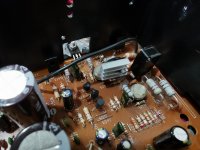
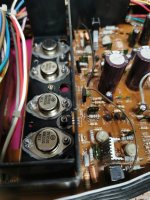
I have already mounted heatsinks (as stated earlier in this thread)
After seing that Q408 and Q407 were getting a lot hotter than all the others I also mounted some salvaged heatsinks on them (couldn't find locally any heatsink for this package)
I guess I just don't really know what's 'working ok' hot and what's 'too hot' hot. Ian Finch's description of more than warm is about right though. I can keep my fingers on the heatsink even after playing music, but they sure are hot.
Because one of the heatshinks is for a different package I had to mount it horizontally.
Attachments
- Status
- This old topic is closed. If you want to reopen this topic, contact a moderator using the "Report Post" button.
- Home
- Amplifiers
- Solid State
- NAD 7020i sudden death