Re: thermal properties of Hometaxial transistors.
We've been advised several times in NAD threads over the years, that epitaxial transistors absolutely need emitter resistors to maintain bias stability. Meaning if you don't fit them when you change epi for hometaxials, your bias will drift all over the place and out of control as temperature changes. This could just mean harsh sounding due to not enough bias or it could also end in thermal runaway and failure.
In my ignorance when I first tried replacing original semis in NADs with epitaxials, it was only a matter of minutes before a repeat meltdown occurred - this was not only embarrassing but expensive so it really is unwise to try your luck.
In contrast, hometaxial transistors do not need emitter resistors for stable bias current and like many early power amplifier designs where they were used, they are generally safe without them. That's what the 3020 was designed around, hence I don't see anything questionable in Jaycees's reply.
For those interested in the historical facts and figures of early silicon audio power, here's some dirt on 2N3055, with its various known US and European manufacturers and reference part numbers of unspecified "taxy". 2N3055 - Wikipedia
In post 28 on page 3 zenzaman said he would rather not mess around with the pcb. I take this as fitting emitter resistors would be the last resort.
He managed to set the output current to specification but he was concerned the drivers were too hot to touch.
These also appear to have survived the fault which took out the outputs and there is no mention of these having been replaced.
I suspect the base emitter junctions in the outputs developed a brief short before going open circuit which likely compromised the drivers.
Last edited:
Agreed. Neither the OP or anyone else would choose to hack the PCB with impunity but is there any option if we want a reliable amplifier from our economic DIY fix? Here in Oz, the original hometaxial parts are now effectively unobtanium because stocks either no longer exist, they're hoarded by collectors or they are too difficult, risky or expensive to buy in small quantity as replacement parts.
If I were determined to get the original hometaxial versions where zenzaman is located, I'd look at the old local sources of 2N3055 equivalents that are known to have been produced in Eastern Europe long ago (see the 2N3055 wiki for clues) but I wouldn't hold much hope for the PNP (MJ2955) equivalents.
As an aside, its also interesting that member John Ellis is named as co-author of a 2N3055 case study doc. I searched while checking sources of info. Maybe I should be paying more attention to the comments and suggestions made here .
.
The 2N3055: a case history - IEEE Journals & Magazine
If I were determined to get the original hometaxial versions where zenzaman is located, I'd look at the old local sources of 2N3055 equivalents that are known to have been produced in Eastern Europe long ago (see the 2N3055 wiki for clues) but I wouldn't hold much hope for the PNP (MJ2955) equivalents.
As an aside, its also interesting that member John Ellis is named as co-author of a 2N3055 case study doc. I searched while checking sources of info. Maybe I should be paying more attention to the comments and suggestions made here
.The 2N3055: a case history - IEEE Journals & Magazine
Last edited:
@zenzaman,
You might be interested in removing the fuses protecting the output transistors, connecting a speaker to the output and see if you can match what can be seen from just before the 6 minute mark in this youtube video
NAD 3020 Helpdesk: Blown Fuses and Output Transistors Repair, Fix - YouTube. That should tell you whether or not your drivers are working OK. If you are worried about this fit a resistor say 100R in series with the speaker for a start.
Nice video and professional attitude. Note that it's a different PCB and layout to the OP's and he's most likely replaced the original RCA hometaxials with those epitaxial ST Micro versions - a mixture of types that may actually work OK up to medium power. You don't see or hear it delivering more than perhaps a couple of watts so we don't know what happens at higher power when the power devices become hot. I've learned not to return amps to the owner in that shape without a full measured power check. Otherwise they can bounce.
Agreed. Neither the OP or anyone else would choose to hack the PCB with impunity but is there any option if we want a reliable amplifier from our economic DIY fix? Here in Oz, the original hometaxial parts are now effectively unobtanium because stocks either no longer exist, they're hoarded by collectors or they are too difficult, risky or expensive to buy in small quantity as replacement parts.
As far as I can see On semiconductor have a 2N3055A but the complementary 2N2955A is no longer being made.
Going back to 1978 RCA sold a hometaxial 2N3055 as well as the epitaxial version but as long ago as that there was no complementary hometaxial MJ2955.
Do you have a wizard in oz where you can get help
He managed to set the output current to specification but he was concerned the drivers were too hot to touch.
When I first started to identify all parts gone bad, the only shorted transistors were Q416 and Q418 (2N3055 and MJ2955). Everything else checked ok, but I also replaced all BD139 transistors with similar new ones ( https://ro.mouser.com/ProductDetail/511-BD139-16/ ), 2SD669A with https://ro.mouser.com/ProductDetail/512-KSC2690AYSTU/ and 2SB649A with https://ro.mouser.com/ProductDetail/512-KSA1220AYS/
After seing that Q408 and Q407 were getting a lot hotter than all the others I also mounted some salvaged heatsinks on them (couldn't find locally any heatsink for this package).
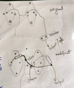
I've attached a drawing with my understanding of the mod needed. I'm inclined to take the easier route, with cutting the traces in the right places, 'surface mounting' the resistors and connecting them with leads, rather than drilling the PCB (as that would require removing the heatsink and outputs again). Besides, I don't really understand the advantages of drilling holes for the resistors, since there are no unused, isolated copper traces for them to be soldered to, and also there seems to be plenty of solder (thickness wise) to cover the resistors' legs really well).
I'm sure I've seen a couple of pics with this mod somewhere around but can't find it anymore (they were for earlier models but could have helped me as inspiration)
Attachments
You have the idea.
Parts soldered to the trace on the surface tend to fall off when the product is jostled in handling. 3 to 5 watt resistors are not light.
Parts on the opposite side of the board with a lead run through a drilled hole and bent over the trace then soldered are better supported against jostling. A kink can be bent in the lead on the component side to clamp the part in place mechanically from both sides.
The interference with the heat sink is the reason I suggested putting the extra resistors over in the blank area with the two big holes. Wires can be run over there. 2 wires instead of one. My ST120 amp the entire transistors are remote from the driver board, 1" away. Emitter resistor flies in the air.
I think you mean MJ2955 as there there never was a TO3 2N2955 that I'm aware of. You get hits with a browser search but when you follow the links, this is what you actually get: datasheet 2N2955As far as I can see On semiconductor have a 2N3055A but the complementary 2N2955A is no longer being made........
.....Do you have a wizard in oz where you can get help
I don't repair old solid state gear now but if necessary, I would be pragmatic and just use epitaxials with emitter resistors as we're discussing. It's not quite the same sound quality as original, and that's what you need to make valid comparisons but most people have been pleased just to have their old treasure working again.
Nice video and professional attitude. Note that it's a different PCB and layout to the OP's and he's most likely replaced the original RCA hometaxials with those epitaxial ST Micro versions - a mixture of types that may actually work OK up to medium power. You don't see or hear it delivering more than perhaps a couple of watts so we don't know what happens at higher power when the power devices become hot. I've learned not to return amps to the owner in that shape without a full measured power check. Otherwise they can bounce.
You are suggesting here the 2N3055s are hometaxial.
If so the gain bandwith product would differ in each output half, and the amplifier. There would be competing poles.
You cannot compensate for dual poles so in that situation the amplifier would be unstable even with no input.
I don't see this amplifier achieving the claimed THD spec of <0.02% unless the outputs are epitaxial devices.
You have the idea.
Parts soldered to the trace on the surface tend to fall off when the product is jostled in handling. 3 to 5 watt resistors are not light.
Parts on the opposite side of the board with a lead run through a drilled hole and bent over the trace then soldered are better supported against jostling. A kink can be bent in the lead on the component side to clamp the part in place mechanically from both sides.
The interference with the heat sink is the reason I suggested putting the extra resistors over in the blank area with the two big holes. Wires can be run over there. 2 wires instead of one. My ST120 amp the entire transistors are remote from the driver board, 1" away. Emitter resistor flies in the air.
Got it now. Thanks!
Mr. Finch has clearly told you the units he repaired did not have RCA parts after the very early ones. MJ2955 did not have to come from Motorola, the part number was not copyrighted. There were lots of little semi houses pushing obsolete parts 1978-1985. Homotaxial MJ2955 would be such an obsolete process, and quite profitable to NAD that covered the earth in their trashy emitter resistor lacking cheap amplifiers. Sourcing homotaxials would be a serious competitive advantage, at a time inflation was cramping everybody's style. Bookshelf speakers were all the rage then, 1 to 3 watts were great for Simon & Garfunkle or Joan Baez LP's. 3 W resistors didn't fit the same pick & place machine head as 1/4 watt resistors, and avoiding that changeover of process machine probably saved $2 a unit production cost. NAd saved another $3 by not having a idle bias pot adjustment that had to be handled by a human being.You are suggesting here the 2N3055s are hometaxial.
If so the gain bandwith product would differ in each output half, and the amplifier. There would be competing poles.
.
People that are willing to pay $3300 for a NAD on Ebay (last week asking price) are preserving the delusion of "quality".
Last edited:
You have the idea.
Parts soldered to the trace on the surface tend to fall off when the product is jostled in handling. 3 to 5 watt resistors are not light.
Parts on the opposite side of the board with a lead run through a drilled hole and bent over the trace then soldered are better supported against jostling. A kink can be bent in the lead on the component side to clamp the part in place mechanically from both sides.
The interference with the heat sink is the reason I suggested putting the extra resistors over in the blank area with the two big holes. Wires can be run over there. 2 wires instead of one. My ST120 amp the entire transistors are remote from the driver board, 1" away. Emitter resistor flies in the air.
This advice is short on detail. There is nothing on resistor values, if these are wire wound, how these will affect power output and how the collector and emitter currents will be laid out to cancel radiated fields due to output stage switching. This looks too much like a Heath Robinson fix.
In post 17 I suggest .47 ohm emitter resistors. I used .51 in my AX6. There are successful epitaxial transistor amps with .33 ohm, .22 ohm, and possibly even .1 ohm emitter resistors.
You can see pictures of how I flew the wiring from driver board to output transistors on the heat sink in this AX6 post #212: Retro Amp 50W Single Supply - Page 22 - diyAudio
Keeping the OT wires 1" away from each other, and keeping the temperature sense wires 2" away from output transistor wires, are key IMHO avoiding oscillation. You'll see my base & emitter wires were 4" long so I could flip the driver board over for work on each side. The high current stuff is IMHO, not sensitive to position or length inside the RF free case. Of course, the NAD has no temperature sense diodes or transistor to cause oscillation with the VAS.
Note nigel7557 or whatever has had trouble with oscillation in Maples (?) 1970's amps that came with homotaxial transistors. His solution was to put 10 ohm 1 watt resistors in the base line to the output transistors. I did that as a damage limitation during meltdown practice, when I replaced the 1970 RCA transistors (burned ) with NTE60's (MJ15003 white box?) epitaxials in my dynakit ST120. I replaced the wires from the driver board to the bases of the transistors over on the heat sink, with 10 ohm 1 watt resistors. Flying right out in the air. If the OP gets oscillation, I suggest that is the next step. As I suggested in post 14.
Last edited:
Yes, also look at this thread: NAD 3020 (& related NAD output stages) . Does the OP there seem familiar?
This same problem with the 3020 series NAD design and the simple emitter resistor solution with suggested resistor values have been covered here time and again (particularly around holiday time ) for the 20 years the forum has been running and in my amateur repairer experience at least, its been done successfully for even longer.
This same problem with the 3020 series NAD design and the simple emitter resistor solution with suggested resistor values have been covered here time and again (particularly around holiday time
) for the 20 years the forum has been running and in my amateur repairer experience at least, its been done successfully for even longer.
Last edited:
BTW, my 50 w retro AX6 amp,with single pair NTE60 output transistors & .51 ohm wirewound emitter resistors (added), a 70 v rail, put out 24 VAC for 5 seconds at a time on SP2-XT "8 ohm" speakers. That is 72 watts. Test done with Simpson 266-XLPM analog voltmeter which measures average AC voltage. I do have heat sinks on the drivers & vas, which Apex doesn't specify on the AX6. VAs was a GE D44R4 from the '70s and drivers were On semi MJE15028/29. All 30 mhz Ft TO220 transistors. Idle bias current was adjusted to 20 ma, so there was no output transistor switching.if these are wire wound, how these will affect power output and how the collector and emitter currents will be laid out to cancel radiated fields due to output stage switching. This looks too much like a Heath Robinson fix.
Last edited:
Mr. Finch has clearly told you the units he repaired did not have RCA parts after the very early ones. MJ2955 did not have to come from Motorola, the part number was not copyrighted. There were lots of little semi houses pushing obsolete parts 1978-1985. Homotaxial MJ2955 would be such an obsolete process, and quite profitable to NAD that covered the earth in their trashy emitter resistor lacking cheap amplifiers.
The comment was made in the context of the NAD 3020 in the youtube video where the output devices were made by RCA and ST Micro inferring a hometaxial device in harness with an epitaxial one.
The RCA hometaxial was rated at 150W and used in consumer and industrial products and probably within the military.
There would be need to service older appliances and equipment relying on these in workplaces etc. You would have a situation of supply and demand and hoarding by the bigger players whom NAD as a relative infant would never have been able to compete with.
Last edited:
In post 17 I suggest .47 ohm emitter resistors. I used .51 in my AX6. There are successful epitaxial transistor amps with .33 ohm, .22 ohm, and possibly even .1 ohm emitter resistors.
Of course, the NAD has no temperature sense diodes or transistor to cause oscillation with the VAS.
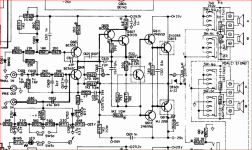
See attached image of NAD7020 circuit for elaborated amplified diode formed around Q609
Attachments
- Status
- This old topic is closed. If you want to reopen this topic, contact a moderator using the "Report Post" button.
- Home
- Amplifiers
- Solid State
- NAD 7020i sudden death