Hi All,
I am slowly powering up an old Peavey PA-200 in unknown working condition. The boards and connections look ok (no signs of arcing or other damage), so I am slowly bringing up the mains power with a dim bulb tester (DBT) and Variac. I am starting with a 40 watt bulb, and my chain is wall -> Variax -> DBT -> amp. I have a speaker hooked up to the output as well.
Everything seems to be fine until around ~40VAC on the input, at which point there is a "pop" in the speaker and it starts to hum. The bulb is not lit at this point.
Is this expected? Should I keep cranking up the input AC, or is this hum indicative of an issue (bad filter caps)?
Any help is greatly appreciated.
Don't use a load when test using a bulb tester.
Remove speaker and use a voltmeter, d.c scale, at the output.
Repeat test looking at the voltmeter and the bulb.
If you don't see high d.c (higher than 100mV)not a bright bulb, not something smell... remove the bulb and test again.Finaly remove the variac and repeat.
Now it is time for speaker attachments.
If a second voltmeter is available you can measure idle current at the same time.
Just huke up to one of the power transistors emitter resistor and you will have the idle current under control simultaneously wirh the output d.c.
Anything about 20mV expected for idle current.
I hope this will be useful.
Good luck!
Many amplifiers will not start up properly through a DBT or variac with a speaker connected. There is often a range of supply voltage below which the amplifier’s offset voltage is too high for the feedback to correct it, or perhaps even become unstable. It may or may not “snap out” of it as the supply is slowly increased - if it has a load. With no load it should - if it’s working properly. Bring it up without the speaker, and once you’ve verified that there is no significant DC offset, connect the speakers. Then you can run it at low volume to verify normal operation. If you can’t bring it up properly without the speaker, address that problem first.
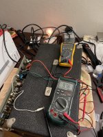
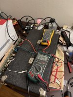
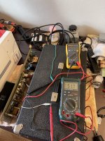
Thanks for the tips everyone. I removed the speaker and added another meter to look for VDC across the output (white and green leads in attached picture, red and black are measuring VAC input from Variac). I measure >100mV DC pretty much instantly after turning up the Variac past a few VAC. Does this indicate an issue? If so, where should I start troubleshooting next?
See link here for schematic and here for manual. Thanks again!
See link here for schematic and here for manual. Thanks again!
Attachments
200 mv dc on speaker is kind of a a limit.
If it doesn't go over that as variac comes near line voltage, I'd plug a music source like a FM radio earphone jack in the input and start looking for AC volts on the output. That is if the light bulb in series with the AC line doesn't light up.
Keep the radio turned down, PA level is usually 1.6 or 2 vac input and a radio earphone will go to 7 maxed out. Don't use a cell phone, unless you can afford to throw it away if DC comes out the input of a dodgy amp and blows it. Used battery FM radios are about $4 at resale shops. Usually with a bad battery clip and maybe a dodgy volume pot. New 10k trimpots are $.50.
DVM produce random numbers on AC scale on music, except for the $160 RMS variety. Those RMS meters will totally miss an ultrasonic oscillation, so I never bought one. I use an analog voltmeter for music tracing, 2 vac scale in the front and 20 vac scale vas or after and nearer the speaker. Put a .047 uf cap series the negative probe with a clip lead to speaker ground. Analog AC voltmeter will read DC voltage on AC scales without the cap. Analog voltmeter can be bought for about $25-30. 20 kohm/volt is about standard, 5k for AC scales. Less sensitive VOM are only useful after the VAS, not near the input tone/control sections.
Otherwise, for music tracing use a scope, and the $50 probe which has to be replaced if you step on it. I fix my equipment without a scope, except for low level hum which an AC vom won't see.
High steady AC voltage on AC voltmeter that doesn't pulse with the beat of rock music, is probably ultrasonic oscillation. That can be checked with a 390 pf cap instead of the .047 uf one. Ultrasonic will blow right through a xxx pf cap, music will be blocked.
Last edited:
DC on out can be bad transistor, but 1 v indicates something marginal, not a huge meltdown.
Your schematic is missing the output stage page.
I'd look at the line out jack which is at the sum of the inputs, with the output putting out 1 v dc. If there is substantial DC on line out, one of the many electrolytic coupler caps from input stages may be leaking.
At this age, all rubber sealed wet caps (electrolytic) are suspect. Could also be a bad solder joint in the output stage, or a resistor burnt up or something. If there is a speaker coupler cap, a 2200 or 3300 uf or something, it could be leaking DC current.
I was able to bring the amp up to 107 VAC on the input, at which I maxed out the Variac (probably due to the bulb in series?). The voltage across the output was about 10 VDC @ 107 VAC input, but was as high as ~12.5 VDC @ ~92 VAC input. The DC voltage slowly drops over time, but this is still abnormally high, right? The bulb is glowing, but I wouldn't necessarily call it "brightly lit".
What should I try next? Should I just replace all electrolytic caps to rule them out? There are only ~5 or so, although there is that big cap can as well...
Also, haven't been able to find a schematic of the output section, does anyone have one per chance?
What should I try next? Should I just replace all electrolytic caps to rule them out? There are only ~5 or so, although there is that big cap can as well...
Also, haven't been able to find a schematic of the output section, does anyone have one per chance?
Attachments
Yeah, I’d start with electrolytics - if you have an output coupling cap that may be part of the problem. If there is an output cap you need to verify what the DC is on the other side of it. It should be about half the supply voltage. If there is no output cap, you need to dig to see what is causing the offset.
The bulb is glowing brighter than I would be comfortable with for an amp operating normally. That’s what keeping the voltage down to 107. Can you measure the bias in the output stage? Do that by measuring voltage across the emitter resistors and ohms law. Once you verify there is not excessive current you can move on from there.
The bulb is glowing brighter than I would be comfortable with for an amp operating normally. That’s what keeping the voltage down to 107. Can you measure the bias in the output stage? Do that by measuring voltage across the emitter resistors and ohms law. Once you verify there is not excessive current you can move on from there.
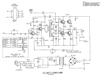
You seem to have a capacitor out single supply transformer driven power amplifier.
Can´t find its specific schematic but it "should" be close to this one:
[see attachment below]
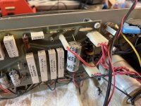
Please confirm , I seem to see in your pictures a large "coffee can" main capacitor and a smaller board mounted axial cap, plus a driver transformer.
If so,it should be close enough.
Component designations might vary, but general structure should be similar.
Do not start by replacing caps, specially some expensive ones, at random, first you must troubleshoot, this is not a guessing game.
1) for now do not connect speaker or any load
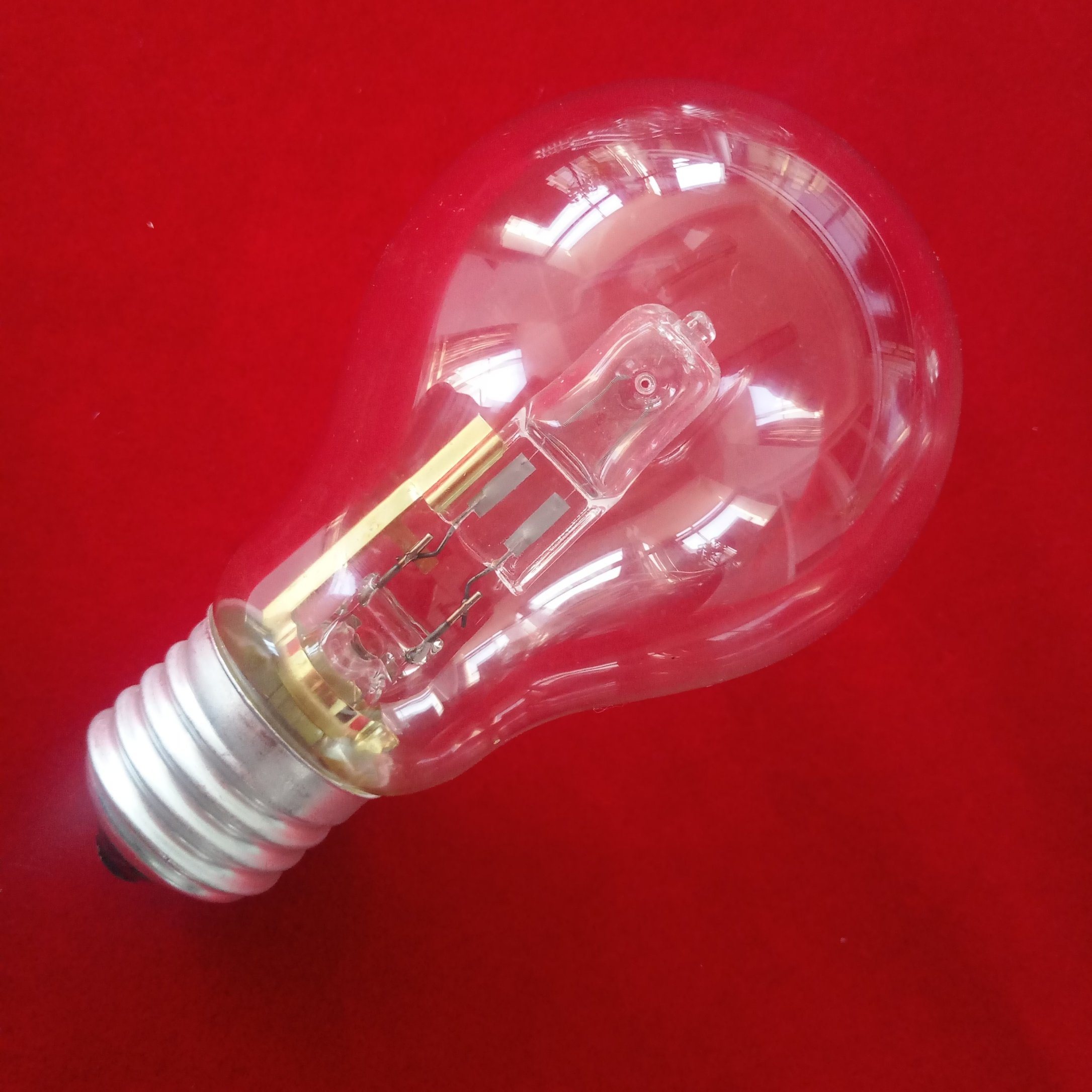
2) what size bulb are you using? Too small it will always glow quite bright.
I suggest 40/60W .
"Real" Watts, not "equivalent":
Old style 60W:
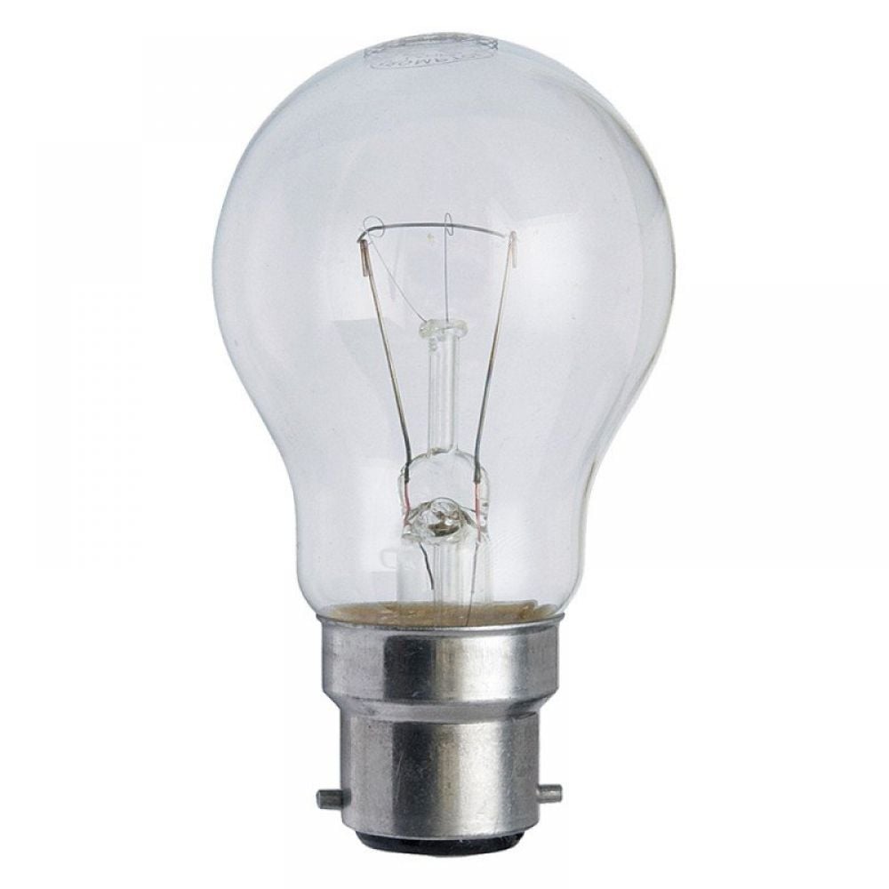
Modernish higher efficiency "75W" bulb inside a bulb, actual 60W
we want a red hot wire inside.
3) connect amp to mains straight through dim bulb, no Variac.
4) all controls to 0, no signal input, measure DC voltages.
Specially +75V +V and +37V "halfway", at the positive of output capacitor.
For now I do not worry much about voltage at speaker out.
Please post voltages measured, which will be some 20% or 30% lower than expected, because DBT will eat some of your mains.
IF DBT shines *bright* , or you see smoke or smell very overheated components , turn amp OFF and post results.
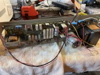
Also a better PCB picture, end to end and showing all components clearly.
Can´t find its specific schematic but it "should" be close to this one:
[see attachment below]
Please confirm , I seem to see in your pictures a large "coffee can" main capacitor and a smaller board mounted axial cap, plus a driver transformer.
If so,it should be close enough.
Component designations might vary, but general structure should be similar.
Do not start by replacing caps, specially some expensive ones, at random, first you must troubleshoot, this is not a guessing game.
1) for now do not connect speaker or any load
2) what size bulb are you using? Too small it will always glow quite bright.
I suggest 40/60W .
"Real" Watts, not "equivalent":
Old style 60W:
Modernish higher efficiency "75W" bulb inside a bulb, actual 60W
An externally hosted image should be here but it was not working when we last tested it.
we want a red hot wire inside.
3) connect amp to mains straight through dim bulb, no Variac.
4) all controls to 0, no signal input, measure DC voltages.
Specially +75V +V and +37V "halfway", at the positive of output capacitor.
For now I do not worry much about voltage at speaker out.
Please post voltages measured, which will be some 20% or 30% lower than expected, because DBT will eat some of your mains.
IF DBT shines *bright* , or you see smoke or smell very overheated components , turn amp OFF and post results.
Also a better PCB picture, end to end and showing all components clearly.
Attachments
Thanks JM; I will report back with voltage readings. I am using a 40W incandescent bulb in my tester. See below for additional images of the power board.
Just to confirm, the big can is the 3500 uf in your attached schematic, correct?
Just to confirm, the big can is the 3500 uf in your attached schematic, correct?
Attachments
Yes.
The two largest caps there are the main filter one: 3500x80 in my schematic, yours should have *similar* specs, and 1000x50 output coupling one, same considerations.
That is a VERY well made amp, VERY robust, can easily be left as good as new 45 years after it was made, amazing.
The two largest caps there are the main filter one: 3500x80 in my schematic, yours should have *similar* specs, and 1000x50 output coupling one, same considerations.
That is a VERY well made amp, VERY robust, can easily be left as good as new 45 years after it was made, amazing.
Thanks JM; I will report back with voltage readings. I am using a 40W incandescent bulb in my tester. See below for additional images of the power board.
Just to confirm, the big can is the 3500 uf in your attached schematic, correct?
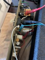
Picture isn't clear but this diode 1N4001 in the left side of the first picture, the uper one looks like hurned
Those two diodes and one of the 15 ohm resistors look pretty iffy. One diode does look bigger than the other - either it is not original, or suspect. Those four components and the two 470/6.3 are the critical bias components for the output stage. You can test the diodes, but if they are crusty I’d replace them. They are cheap, as are the 15 ohm resistors and two caps. The caps may be fine, but Illinois Capacitor from that vintage aren’t exactly the best. They get leaky, but still *work*. Any time I see those old IC caps, they go (they are what always fails in the protection circuits of the big Crest amps. Always). The big wire wound resistors won’t go open circuit unless the board is cooked, and it’s not. If all of those are good, there is nothing left that can result in blown output transistors. The output transistors are easy enough to pull and test, if for some reason you still don’t get about 37 volts (half the supply) on the hot side of the output cap. Either they are all good, or replace all. They are probably house numbered selected 2N3055’s, but I would use 2N3773’s or better. But if they are good, leave them. If the output cap is leaky replace it. It may be “leaky” if the hot side is stuck to the rail voltage due to an output transistor or bias circuit failure, but ok at normal voltage. I would use a bigger one to get better bass response, but you may want the original size to protect small speakers against low frequency overload like dropped mics.
If the last stage is clean you can move on to the two stages that drive it. They are isolated by the transformer and anything wrong here can’t result in a catastrophic cascade failure, like they can with more “modern” designs. That’s one reason why these old things were nearly bulletproof.
If the last stage is clean you can move on to the two stages that drive it. They are isolated by the transformer and anything wrong here can’t result in a catastrophic cascade failure, like they can with more “modern” designs. That’s one reason why these old things were nearly bulletproof.
Checking is fast and costs nothing. Do the checking of voltage first. That will determine whether the problem is inside the output cap (1000 uf 50v) (Bias or transistors) or the output cap itself.
In the end you'll want to replace all those ancient e-caps. The total value of caps is about $8, the freight from thief river falls mn or north carolina is $10. So buy them all at once, but replace one at a time and see if you made the amp better, or worse. Amateurs (including me) make a lot of bad solder joints. If you replace too many things without measurements, you don't know where you just inserted a problem. If you do one part, and it gets worse, you know just where the problem is.
Also checking the diode wg-ski complained about is a simple resistance check. Also the resistors he complained about. Color is nothing, resistance value is important. Diodes are of course 600 to 700 mv forwards, 9999 or ---- backwards. Backward won't be fully 9999 because the cap will charge up the parallel capacitor. If your DVM doesn't have diode scale, use the 2000 ohms scale (on mine).
If you take measurements, you'll get everything you need in one $10 box, instead of making several orders. If output transistors are bad, or diodes or other secondary components, you should find out now. Fortunately as wg-ski said, the transformer between input & output limits the size of output meltdowns. My direct connected PV-1.3k, it took 127 small parts to repair it because the rail voltage went all the way back to the DDT parts one step from the input.
IMHO parts from a local storefront have been lower quality than the parts I get from newark, digikey, or mouser. I can buy 5000 to 10000 hour rated electrolytic caps, instead of the 500 hour caps I used to have to buy at the TV parts store. Those had to be replaced 3 times since 1970.
Last edited:
I measured ~+52VDC at both measurement points (across the cap can and from the positive of the 1000uf cap to ground, see picture). Bulb glowed brightly initially, then dimmed.
The two diodes and 15 ohm resistors appear to be toast (diodes measured ~0V forward voltage and resistors had ~3 ohm resistance).
Should my next step be to replace components one at a time as suggested by indianajo?
The two diodes and 15 ohm resistors appear to be toast (diodes measured ~0V forward voltage and resistors had ~3 ohm resistance).
Should my next step be to replace components one at a time as suggested by indianajo?
Attachments
Good eyePicture isn't clear but this diode 1N4001 in the left side of the first picture, the uper one looks like hurned
")
It looks burst.
Also the first 470 x 6.3 grey capacitor on its left looks burst, its rubber seal looks dirty with salts, compare it to the one to its left.
In due time all electrolytics must be replaced, but it´s good practice FIRST to find current problem, simply to reduce number of variables, and then tidy it up.
That said, those visibly damaged of course must be replaced now.
Check NOW, among other reasons so we can guess that is the actual problem.Thanks thimios and wg-ski. Should I replace the diodes and 470/6.3 caps before checking the +75 and +37 voltages?
Whay in you replace them, do other things and then it "works". You´ll never know whether you actually repaired it or itb started working by resoldring , moving wires or connectors, whatever.
Like Enzo says: "do not find excuses to NOT check something"
Besides, as indianajo says, it takes esconds.
And then RECHECk after you replaced them.
Replacing parts is easy, main job is troubleshooting, finding what/why something happened.
EXCELLENT advice.If you replace too many things without measurements, you don't know where you just inserted a problem. If you do one part, and it gets worse, you know just where the (new) problem is.
That hints at shorted top transistor, or open/unbiased bottom one, or open bottom emitter resistors.I measured ~+52VDC at both measurement points (across the cap can and from the positive of the 1000uf cap to ground, see picture).
Start by replacing visibly broken diode, anyway check that both drop about 700mV on diode test and replace visibly leaky 470uF cap.
To avoid ordering parts "one by one", you "should" have 1N400x diodes available, absolute worst case recycle one from a dead/abandoned power supply and replace cap by "any" cap you have, from 100uF up.
**all this just for testing** to know what to order.
If way out of value , also replace the 15ohm resistor.
If no 15 ohm resistor in stock, make it out of 2 x 33 ohm ones in parallel, 10+4.7 ohm in series, etc, its value is critical in thye series biasing string from +V to ground.
Voltages might go back to normal (although *something* made those parts burst) or transistors might be damaged (top ones shorted or bottom ones open) or bottom emitter resistors might be open.
Measure voltage from bottom transistor emitters to ground.
ABSOLUTE WORST CASE replace everything to the right of the driver transformer but you may be spending some money on power transistors which *might* be fine.
Last edited:
- Home
- Amplifiers
- Solid State
- Peavey PA-200 Powerup With Dim Bulb Tester and Variac